Getting started – MicroNet Technology Network Device RAIDBank4 User Manual
Page 9
RAIDBank4 Owner’s Manual
9
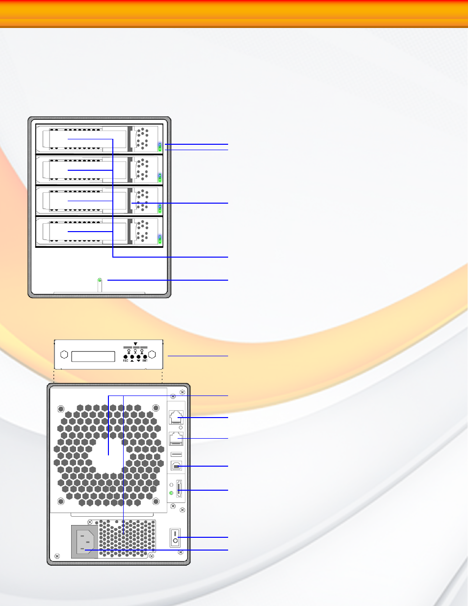
The RAIDBank4 interface components
The following figures illustrate the connector locations for the RAIDBank4.
FRONT VIEW
1-Getting Started
REAR VIEW
Disk Activity LED
Disk Power LED
Power/Status Indicator Light
LCD Panel with Keypad
Fan vents (DO NOT BLOCK!)
RS232 Port (reserved)
LAN monitoring Port
Host USB Port
Host eSATA Port
Master Power Switch
AC Power Connector
Canister Release Latch
Disk Canisters