McIntosh MA6600 User Manual
Page 6
6
Installation
Installation
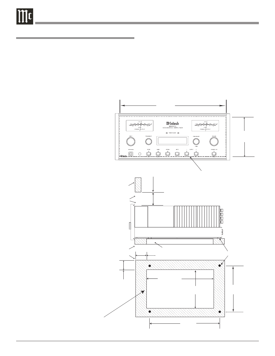
The MA6600 can be placed upright on a table or shelf,
standing on its four feet. It also can be custom installed
in a piece of furniture or cabinet of your choice. The four
feet may be removed from the bottom of the MA6600
when it is custom installed as outlined below. The four feet
together with the mounting screws should be retained for
possible future use if the MA6600 is removed from the
custom installation and used free standing. The required
panel cutout, ven-
tilation cutout and
unit dimensions are
shown.
Always provide ad-
equate ventilation
for your MA6600.
Cool operation
ensures the longest
possible operating
life for any elec-
tronic instrument.
Do not install the
MA6600 directly
above a heat gen-
erating component
such as a high
powered amplifier.
If all the compo-
nents are installed
in a single cabinet,
a quiet running
ventilation fan can
be a definite asset
in maintaining all
the system compo-
nents at the coolest
possible operating
temperature.
A custom cabinet
installation should
provide the follow-
ing minimum spac-
ing dimensions for
cool operation.
Allow at least 6 inches (15.24cm) above the top, 2 inches
(5.08cm) below the bottom and 1 inch (2.54cm) on each
side of the Integrated Amplifier, so that airflow is not ob-
structed. Allow 20 inches (50.8cm) depth behind the front
panel. Allow 2-1/4 inch (5.72cm) in front of the mounting
panel for handle clearance. Be sure to cut out a ventilation
hole in the mounting shelf according to the dimensions in
the drawing.
SOURCE: CD1
15%
6 -
5/8
"
16.83cm
17-
1/16
"
43.34cm
Cutout Opening for Custom Mounting
MA6600 Front Panel
Custom Cabinet Cutout
Cutout
Opening
for
Ventilation
Cutout Opening for Ventilation
Support
Shelf
Cabinet
Front
Panel
Chassis
Spacers
MA6600 Side View
in Custom Cabinet
MA6600 Bottom View
in Custom Cabinet
14-
1/2
"
36.83cm
1"
2.54cm
6"
15.24cm
Opening
for Ventilation
13"
33.02cm
15-
1/16
"
38.26cm
2"
5.08cm
Note: Center the cutout Horizontally
on the unit. For purposes of
clarity, the above illustration
is not drawn to scale.
13-
5/16
"
33.81cm