Displacement pump, Warning, Caution – Graco Inc. 233940 User Manual
Page 14
310548
14
Displacement Pump
See manual 309277 for pump repair instructions.
Removal
1. Flush pump.
2.
Relieve pressure; page 5.
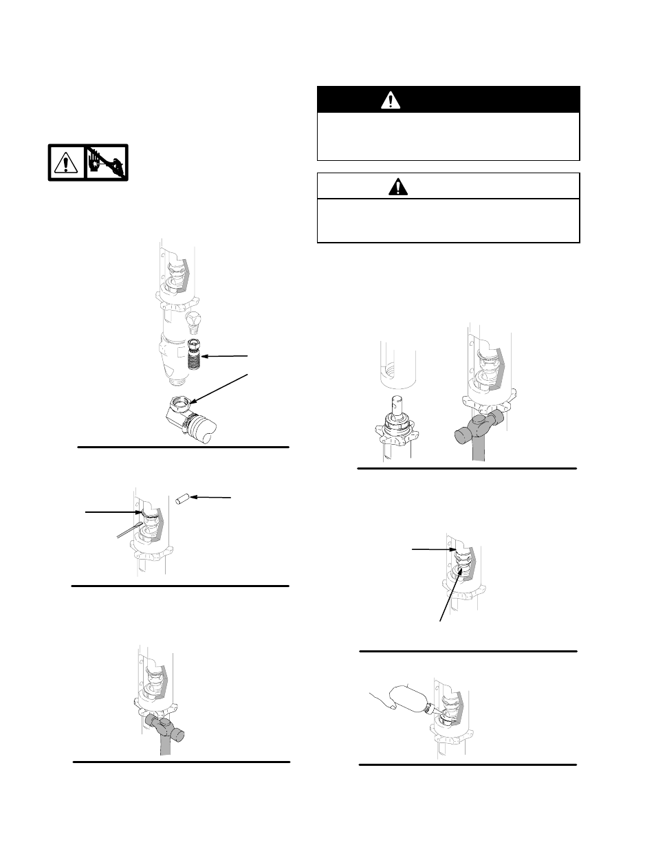
3. Fig. 7. Remove suction tube (114) and paint hose
(63) (remove at swivel end).
Fig. 7
ti2272a
63
114
4. Fig. 8. Push retaining spring up; push out pin (21).
Fig. 8
21
ti2272a
120
5. Fig. 9. Loosen jam nut. Unscrew pump.
Fig. 9
ti2272a
Installation
WARNING
If pin works loose, parts could break off and project
through the air and result in serious injury or prop-
erty damage. Make sure pin is properly installed.
CAUTION
D
If the pump jam nut loosens during operation, the
threads of the bearing housing and drive train will
be damaged. Tighten jam nut as specified.
1. Fig. 10. Screw jam nut to bottom of pump threads.
Screw pump completely into manifold. Unscrew
pump from manifold until pump outlet aligns with
hose. Hand tighten jam nut, then tap 1/8 to 1/4
turn with hammer or torque to 200 ft-lb (270 N·m).
Fig. 10
ti2272a
2. Fig. 11. Slowly pull engine starter rope until pump
rod pin hole is aligned with hydraulic rod hole.
Fig. 8. Push pin (21) into hole. Push retaining
spring (120) into groove.
Fig. 11
ti2272a
pump
rod
hydraulic
rod
Fig. 12. Fill packing nut with Graco TSL.
Fig. 12
ti2272a