Hold-down adjustment, Blade adjustment – Grizzly FOOT SHEAR T23036 User Manual
Page 18
-16-
t23036 37" Foot Shear
Hold-Down
Adjustment
the hold-down functions as a safety device to
secure the workpiece while it is being sheared
and to help prevent the operator's fingers from
getting in the blade cutting path. the hold-down
must be adjusted properly to perform these func-
tions.
the ideal adjustment provides only enough clear-
ance to slide the workpiece under the workstop.
For practicality and safety, the workstop should be
adjusted to provide approximately
1
⁄
8
" clearance.
items Needed
Qty.
Stock
1
⁄
8
" .............................................................1
Socket or Wrench 19mm ....................................1
To adjust the hold-down:
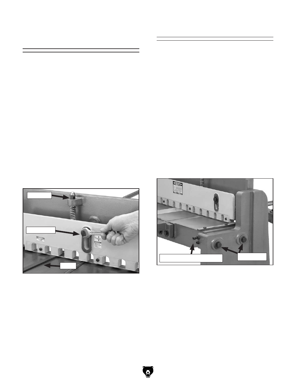
1. tighten the hex nuts on the springs to raise
the hold-down off the table (
Figure 17).
Figure 17. tightening hold-down.
hex nut
Fixing Bolt
Shim
2. insert the shim stock under the hold-down,
then loosen the hex nut to lower the hold-
down until it makes contact with the shim.
3. repeat Step 2 at the other side of the shear.
4. Check the gap to make sure the distance is
equal across the length of the hold-down.
Tip: To avoid scratching the surface of your
workpiece, apply thin rubber pads to the bottom
of the hold-down fingers.
the blade adjustment has been made at the fac-
tory before shipment. A few test cuts will deter-
mine if this adjustment is satisfactory for your
needs. if it is, you are ready to start using your
foot shear. however, you may find it necessary
to check the blade adjustment before continuing.
depending on how often you change the type
and gauge of material you cut, this adjustment
process may become routine.
Tools Required
Qty.
Socket or Wrench 24mm ....................................1
hex Wrench 8mm ...............................................1
Feeler gauge 0.002" ..........................................1
To perform the blade adjustment:
1. loosen, but do not remove the two table bolts
and table adjustment screws on both sides of
the foot shear (see
Figure 18).
blade Adjustment
Figure 18. Adjustment screws.
table Bolts
table Adjustment Screws
2. Using the foot pedal, lower the blade and
hold it in position. (it may help to have your
assistant do this step.)
3. turn the table adjustment screws to move
the table and fixed blade until the fixed blade
makes light contact with the moving blade.
NOTICE: The moving blade should never
overlap the fixed blade. This will cause dam-
age to both.