Assembly – Grizzly FOOT SHEAR T23036 User Manual
Page 14
-12-
t23036 37" Foot Shear
Assembly
Assembling the Model t23036 consists of install-
ing the foot pedal assembly and the front and rear
extension arms assemblies. installation of the
extension arms is an optional step that is depen-
dent on the operations you plan to perform.
To assemble the foot shear:
1. At the lower rear of the machine, loosen the
set screws that hold the hinge pins in place
and slide them outward (
Figure 7).
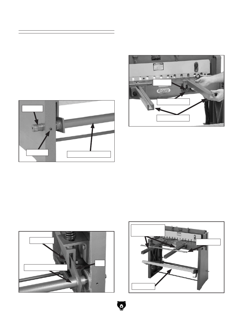
5. loosen, but do not remove the four 19mm
hex bolts on the front of the table.
6. place the front extension arms over the hex
bolts and behind the special washers (
Figure
9).
2. With the help of an assistant, align the foot
pedal assembly with the hinge pin and slide
the hinge pin back in.
3. tighten the set screws to hold the hinge pins
in position.
4. Attach the two blade yokes to the arms of the
foot pedal with the M14-2 x 50 bolts, washers
and nuts, and tighten in position (
Figure 8).
Figure 7.
Hinge pin & foot pedal.
Set Screw
hinge pin
Foot pedal Assembly
Figure 8. Foot pedal assembly.
Blade yoke
Arm
Foot pedal Assembly
Figure 10.
Foot pedal and front extension arms.
Figure 9. Front extension arm installed.
Special Washer
hex Bolt
extension Arms
7. line up the channel of the front extension
arm with the channel on the table.
8. Make sure the ground flat surface on the front
extension arms is flush with the top of the
table surface.
9. tighten the hex bolts and check to make
sure the alignment is still intact. if it is not,
re-adjust as necessary.
10. Slide the front work stop into the extension
arms. When the foot pedal, front exten-
sion arms, and work stops are installed, the
machine should look like Figure 10.
Foot pedal
Work Stops
Front extension
Arms