Media specifications – Genicom microLaser 170 User Manual
Page 99
S
pec
if
ic
ati
o
n
s
8
6
Ze
br
a
Xi
II P
ri
n
te
r U
se
r’s
Gu
id
e
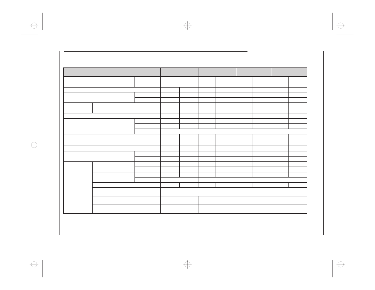
Media Specifications
Media Specifications
90XiII
140XiII
170XiII
220XiII
Total media width (label + liner, if any)
Minimum
Not available at time of
press
1.57”
40 mm
2”
50 mm
4.25”
108 mm
Maximum
5.59”
142 mm
7.17”
182 mm
8.8”
224 mm
Maximum label length (with expanded memory and continuous media) 106”
2692 mm
157”
3988 mm
106”
2692 mm
157”
3988 mm
Total thickness (includes liner, if any)
Minimum
0.003”
0.076 mm
0.003”
0.076 mm
0.003”
0.076 mm
0.003”
0.076 mm
Maximum
0.012”
0.305 mm
0.012”
0.305 mm
0.012”
0.305 mm
0.012”
0.305 mm
Core size
With standard hanger
3”
76 mm
3”
76 mm
3”
76 mm
3”
76 mm
With optional spindle
1.77”
45 mm
1.77”
45 mm
1.77”
45 mm
1.77”
45 mm
Maximum roll diameter
8.0”
203 mm
8.0”
203 mm
8.0”
203 mm
8.0”
203 mm
Inter-label gap
Minimum
0.079”
2 mm
0.079”
2 mm
0.079”
2 mm
0.079”
2 mm
Preferred
0.118”
3 mm
0.118”
3 mm
0.118”
3 mm
0.118”
3 mm
Maximum
Max. inter-label gap = 2
´ (label length for which you’ve calibrated the printer) + 1”
Maximum internal fanfold media pack size (label + liner) L
´ W ´ H
8.00”
´
3.54”
´
4.50”
203
´ 90 ´
114 mm
8.00”
´
5.59”
´
4.50”
203
´ 142 ´
114 mm
8.00”
´
7.17”
´
4.50”
203
´ 182
´ 114 mm
8.00”
´
8.8”
´
4.50”
203
´ 224
´ 114 mm
Ticket/tag notch length
0.079”
2 mm
0.079”
2 mm
0.079”
2 mm
0.079”
2 mm
Effective leading edge registration accuracy
Vertical
±0.040”
±1 mm
±0.040”
±1 mm
±0.040”
±1 mm
±0.040”
±1 mm
Horizontal
±0.059”
±1.5 mm
±0.059”
±1.5 mm
±0.059”
±1.5 mm
±0.059”
±1.5 mm
Additional specifi-
cations for black-
mark media
Mark thickness (measuring
parallel to label/tag edge)
Minimum
0.12”
3 mm
0.12”
3 mm
0.12”
3 mm
0.12”
3 mm
Maximum
0.43”
11 mm
0.43”
11 mm
0.43”
11 mm
0.43”
11 mm
Mark width (measuring per-
pendicular to label/tag edge)
Minimum
0.43”
11 mm
0.43”
11 mm
0.43”
11 mm
0.43”
11 mm
Maximum
full media width
full media width
full media width
full media width
Mark-to-mark leading edge registration tolerance ±0.016”
±0.4 mm
±0.016”
±0.4 mm
±0.016”
±0.4 mm
±0.016”
±0.4 mm
Mark location
Marks must be located within 1 mm of the edge of the media that will be closest to the printer’s mainframe
when loaded in the printer.
Mark density
> 1.0 ODU (Optical Den-
sity Unit)
> 1.0 ODU (Optical Den-
sity Unit)
> 1.0 ODU (Optical
Density Unit)
> 1.0 ODU (Optical Den-
sity Unit)
Maximum density of the back of the media on
which the black mark is printed
0.5 ODU
0.5 ODU
0.5 ODU
0.5 ODU
xi2ch6
Page 8
6
Tuesda
y
, Apr
il
23,
1996
12:
41
PM