Repair – Graco Inc. Series E User Manual
Page 10
10
307–760
REPAIR
WARNING
These repair procedures should be performed only
by qualified repair personnel with an electrical back
ground, using the proper tools. Failure to do the pro-
cedures correctly can result in electric shock, or oth-
er serious injury and damage to the pump.
WARNING
Always follow the Pressure Relief Procedure
Warning on page 8 before attempting any repair.
NOTE: For all electrical repair, follow the Pressure Relief
Procedure Warning on page 8, and then remove
the base plate (42), screws (33) and bumpers
(43). Reinstall these parts, making sure all wires
are tucked in neatly, before checking or operat-
ing the system.
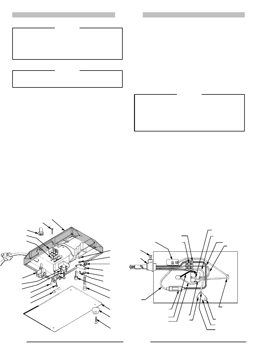
Fuse
(See Fig 10)
1. Remove the old fuse (67) and install a new one. Use
only a 3AG, 1 amp fuse.
Rectifier
(See Fig 1
1)
1. Disconnect the four leads from the rectifier.
2. Remove the rectifier (39).
3. Install a new rectifier so the positive terminal (+) is
closest to the fuse holder (65).
4. Connect the blue lead to an unmarked terminal, and
the pressure switch lead to the other unmarked ter-
minal. Connect the black motor lead to the negative
(–) terminal, and the red motor lead to the positive (+)
terminal.
ON/OFF Switch
(See Fig 10 & 1
1)
1. Disconnect the two leads from the ON/OFF switch
terminals. See Fig 11.
2. Remove the boot (36). Pull the switch (34) out of the
base. See Fig 10.
3. Install the new switch, aligning the tab in the base
with the slot in the switch. See Fig 10. Install the boot.
4. Connect a pressure switch lead to the power-out ter-
minal, and a jumper wire lead to the power-in termi-
nal of the new ON/OFF switch.
WARNING
To maintain grounding continuity in your system, and
reduce the risk of electric shock, be sure the green
ground wire from the power supply cord is properly
connected to the grounding screw (83) as instructed
in Step 4, above. Also be sure the screw (25) is tightly
screwed into the base. See Fig 10 and 11.
Power Supply Cord
(See Fig 1
1)
1. Disconnect the power supply cord leads from the ter-
minal strip (71) by loosening the three screws on the
cord side of the strip. See Fig 11.
2. Loosen the screw in the side of the strain relief bush-
ing (38) and pull out the cord.
3. Strip approximately 6 mm (1/4 in.) of insulation off
each end of the new cord. Install the new cord and
connect the leads to the terminal strip as shown in
Fig 11, being sure that each color lead is across from
a like-colored lead.
4. Install an appropriate, three-pin plug on the other end
of the power supply cord.
65
68
67
41
83
26
28
65
ЙЙЙЙЙ
ЙЙЙ
ЙЙЙ
ЙЙЙ
ЙЙЙ
Fig 10
Fig 11
70
82
26
28
25
42
43
33
31
72
36
71
70
34
39
33
71
70
BLUE
BROWN
YELLOW/GREEN
33b
34
38
PRESSURE
SWITCH (2)
LEADS
25
41
83
BLACK
RED
MOTOR LEADS
39
SCREW
JUMPER
WIRE