I:8d d$agzavn g=c, Replacing control panel light bulbs, Rewiring motor – Grizzly Extreme Series Jointer G9953ZXF User Manual
Page 14
-12-
Extreme series Jointer (Mfg. since 9/11)
6&
6'
.*
.+
.-
LOAD
,
I:8D
D$AGZaVn
G=C"&%
&$'
($)
*$+
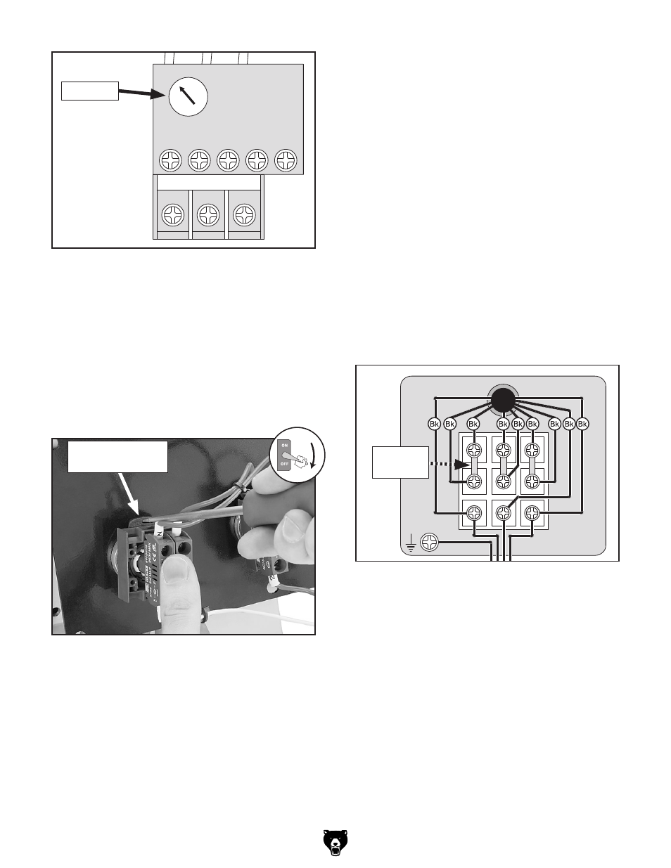
Figure 6. 440V overload relay set at 7 amps.
load dial
4. replace the control panel before connecting
the jointer to power.
Replacing control panel Light bulbs
1. disCoNNECt JoiNtEr FroM poWEr!
2. remove the control panel from the electrical
pedestal to access the rear of the power lamp
and oN button assemblies (see
Figure 7).
Figure 7. accessing the light bulb from the rear
of the control panel.
Button assembly
lock latch
4. replace the motor junction box cover and
access panel before connecting the jointer to
power.
)
*
+
,
-
.
&
'
(
Figure 8. illustration of motor wired for 440V operation. terminal Jumper 3. use a small, flat screwdriver to move the power lamp assembly lock latch to the left, as Figure 7, pull the assembly loose from the panel, then replace the light bulb. 4. re-install the lamp assembly, move the lock latch to the right to secure it. 5. repeat Steps 3–4 for the oN button, then re-install the control panel onto the electrical Rewiring Motor 1. disCoNNECt JoiNtEr FroM poWEr! 2. remove the rear motor access panel, then remove the motor wiring junction box cover. 3. Configure the terminal jumpers as shown in Figure 8.
shown in
pedestal.