Dispenser motor – GE WBVH6240 User Manual
Page 32
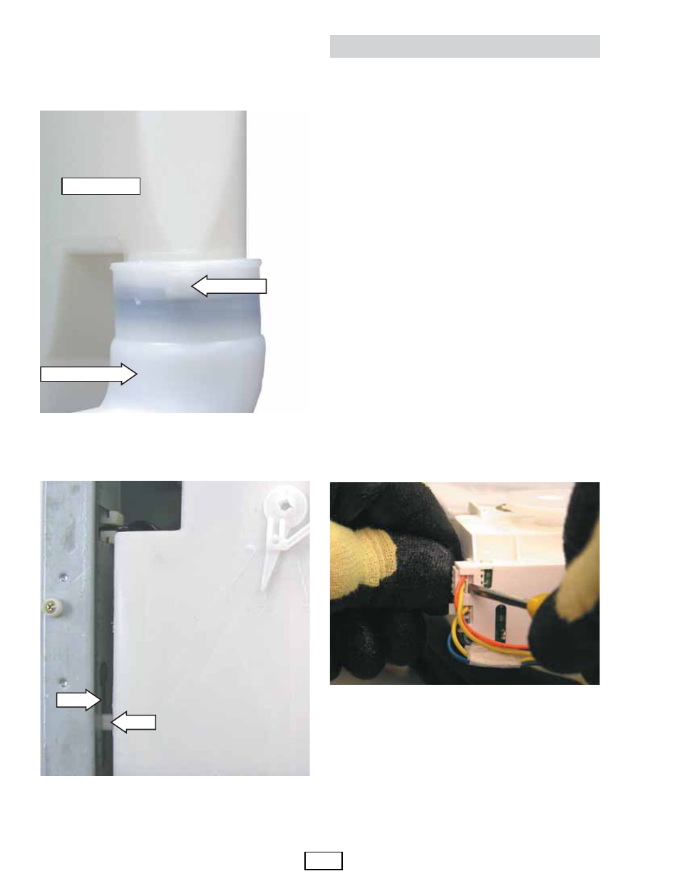
Note: The inlet pipe seal is diffi cult to install, place a
small amount of liquid soap on the seal. Install the
inlet pipe in alignment with the indentation at the
bottom of the dispenser tank.
Note: Ensure the dispenser guide pin is inserted into
the slot in the side of the cabinet left side top brace.
Pin
Slot
Bottom of Tank
Water Inlet Pipe
Indentation
Harness Removal
Dispenser Motor
The dispenser is operated by a 120 VAC, 60 HZ.
motor. The dispenser motor receives commands
from the control board and controls dispenser
operation.
Operation of the dispenser motor can be checked
by using the Service Test Mode t12. (See
Service Test
Mode
.)
Specifi c failures associated with the dispenser
motor can initiate error codes E38, E39, and E62.
(See Service Test Mode.)
To remove the dispenser motor:
Access the dispenser assembly. (See
Dispenser
Assembly
.)
Caution: Lock tabs on dispenser motor wiring
harnesses are fragile. Tab breakage can occur if
excessive release pressure is applied.
Disconnect the 2 wire harnesses from the
dispenser motor.
Note: It can be helpful to insert a small fl at-
bladed screwdriver (as shown) to remove the wire
harnesses.
1.
Remove the 2 Phillips-head screws that attach
the motor and gasket inlet hose clip to the
dispenser tank. (See
Dispenser Assembly
.)
Lift dispenser motor vertically from dispenser
tank.
2.
3.