Boom load positioning instructions, Maximum load centers – Genie SUPERLIFT 97550 User Manual
Page 20
18
Genie Superlift Advantage
Part No. 97550
Operator's Manual
Third Edition • Third Printing
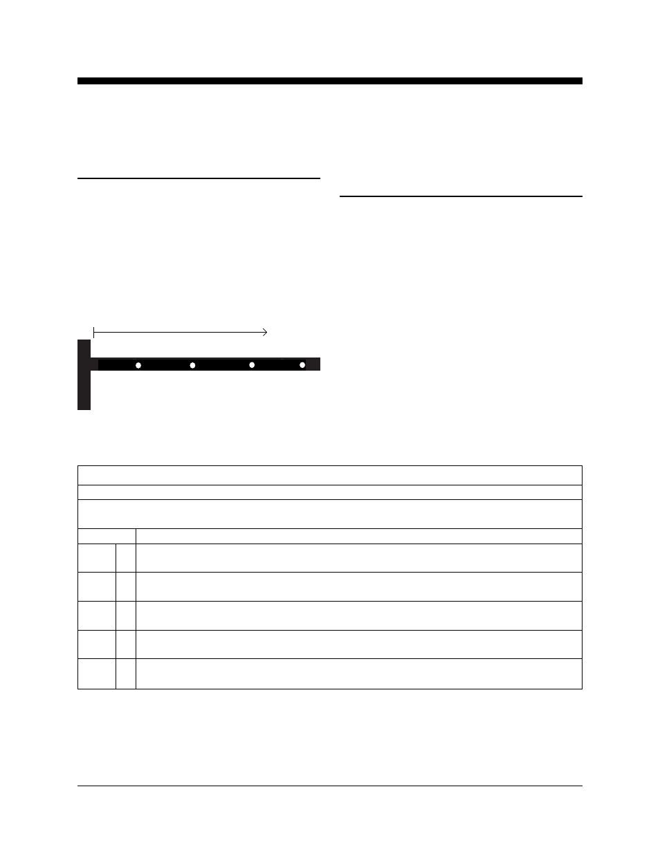
LOAD CAPACITY CHARTS
Boom
Load Positioning Instructions
1 Determine the weight of the load and the
location of its load center.
2 Refer to the chart below to determine if the
machine is capable of lifting the weight at the
location on the boom.
3 Secure the load to the lifting shackle on the
boom.
measure to the load center
18 in
24 in
32 in
42 in
46 cm
61 cm
81 cm
107 cm
Maximum Load Centers
(measure from the front of the carriage)
Standard Forks:
24 in
61 cm
Adjustable Forks:
24 in
61 cm
Boom:
42 in
107 cm
Flat Forks:
28 in
71 cm
Load Platform:
24 in
61 cm
Pipe Cradle:
18 in
46 cm
Fork Extensions:
42 in
107 cm
Load Capacity Chart
Load Center
18
20
22
24
26
28
30
32
34
36
38
40
42
46
51
56
61
66
71
76
81
86
91
97
102
107
Model
SLA-5
1000
1000
1000
1000
938
875
813
750
670
590
510
430
350
454
454
454
454
425
397
369
340
304
268
231
195
159
SLA-10
1000
1000
1000
1000
913
825
738
650
600
550
500
450
400
454
454
454
454
414
374
335
295
272
249
227
204
181
SLA-15
800
800
800
800
763
725
688
650
620
590
560
530
500
363
363
363
363
346
329
312
295
281
268
254
240
227
SLA-20
800
733
667
600
563
525
488
450
430
410
390
370
350
363
332
303
272
255
238
221
204
195
186
177
168
159
SLA-25
650
583
517
450
425
400
375
350
330
310
290
270
250
295
264
235
204
193
181
170
159
150
141
132
122
113
inches
cm
lbs
kg
lbs
kg
lbs
kg
lbs
kg
lbs
kg