5 magnetron heater voltage, Warning – Furuno 1715 User Manual
Page 38
3. INSTALLATION
30
3.5 Magnetron Heater Voltage
Magnetron heater voltage is formed at the
MD Board of the antenna unit and is
preadjusted at the factory. Therefore, no
adjustment is required. However, verify the
voltage as below.
WARNING
ELECTRICAL SHOCK HAZARD
Do not open the equipment.
DO NOT attempt the
procedure below unless
totally familiar with electrical
circuits.
1. Open the antenna cover and open the
shield plate.
2. Turn on the power.
DO NOT transmit.
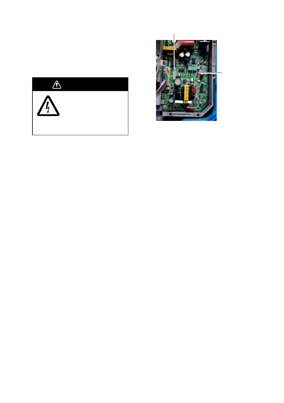
3. Connect a multimeter, set to 10 VDC
range, between #6 (+) and #4 (-) of test
point TP804 on the MD Board.
TP804
VR801
MD board
4. Confirm that the multimeter shows 8.0 V
±0.1 V. If it does not, adjust potentiometer
VR801 on the MD Board.
5. Turn off the power.
6. Fasten the shield plate.
7. Close the antenna cover.
- FAR-2805 Series (169 pages)
- FR-8062 (2 pages)
- FR-8122 (56 pages)
- CH-37 (71 pages)
- CH-37 (90 pages)
- FAR-2XX7 (4 pages)
- FAR-2XX7 (2 pages)
- FELCOM16 (4 pages)
- FRS-1000B (8 pages)
- FRS1000 (8 pages)
- Ls4100 (48 pages)
- 520 (73 pages)
- Marine Radar (24 pages)
- 1944C-BB (233 pages)
- 1733C (260 pages)
- FR-2105 (197 pages)
- FMD-8010 (50 pages)
- GD-1900C (260 pages)
- Black Box Video Sounder FCV-1200BB (2 pages)
- FR-1505 MARK-3 (4 pages)
- 1762 (252 pages)
- NAVnet DRS12A (44 pages)
- FAR-2137S (8 pages)
- FAR-2127 (136 pages)
- FA30 (6 pages)
- Satellite Compass SC-50/110 (30 pages)
- 1715 (2 pages)
- 1734C (55 pages)
- GD-1720C (53 pages)
- Mu 120c (2 pages)
- NAVNET GD-1920C (239 pages)
- CI-80 (41 pages)
- FAR-28x7 Series (299 pages)
- FAR-2837S (8 pages)
- BBWX1 (2 pages)
- 851 MARK-2 (37 pages)
- 851 MARK-2 (47 pages)
- BBFF3 (1 page)
- CSH-53 (106 pages)
- CSH-53 (108 pages)
- FCV295 (53 pages)
- FR1500 Mk3 (79 pages)
- FI-50 Series (2 pages)
- FCV-1150 (32 pages)