3 wiring – Furuno 1715 User Manual
Page 34
3. INSTALLATION
26
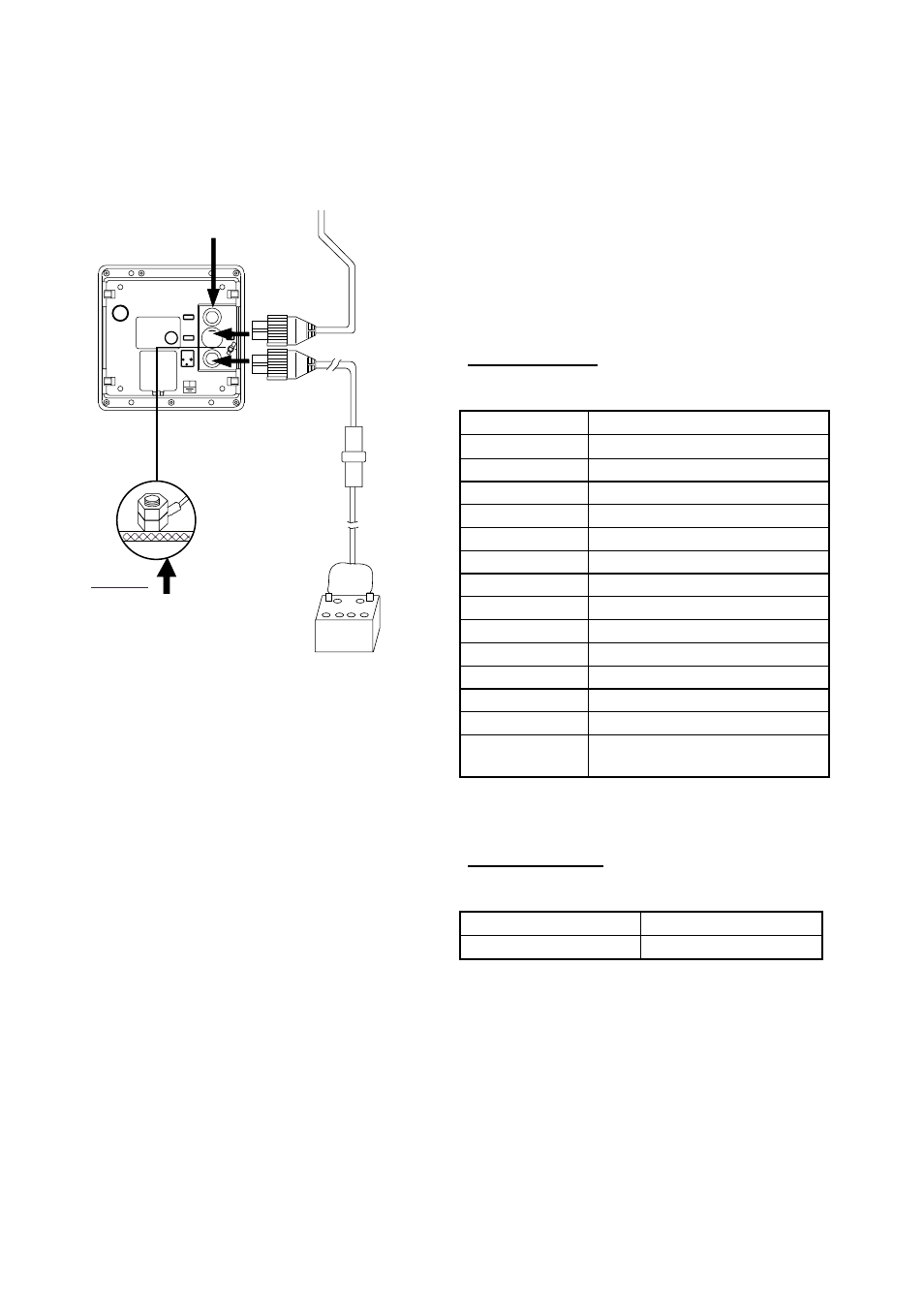
3.3 Wiring
Connect the antenna cable, the power cable
and the ground wire as shown below.
FUSE (5 A)
POWER SUPPLY
12/24 VDC
PO
WER CABLE
DISPLAY UNIT
ANTENNA UNIT
ANTENNA CABLE
*
WHT (+)
BLK (-)
External Equipment
(NMEA)
GROUND
Connect ground
wire to bolt fastened
(or welded) to hull.
* = Do not confuse the
antenna cable with the
transducer cable
for the Echo Sounder
(ex. LS-6100). The transducer
cable is black; the antenna
cable is white and "RADAR"
is written on the cable.
Wiring
Connecting external equipment
A video sounder, navigator, plotter, wind
indicator or GPS receiver GP-310 (320B) can
be connected to the display unit. You will
need an NMEA cable to make the connection.
To connect two navigators, use the optional
cable MJ-A15A7F0004-005. Connect them
referring to the interconnection diagram at the
back of this manual.
Input sentences
NMEA 0183 Version 1.5/2.0/3.0, 4800 bps
Name Sentences
Ship’s Speed
VTG>RMC>RMA>VBW>VHW
Depth DPT>DBK>DBS>DBT
Heading (T)*
HDT>HDG>VHW>HDM
Heading (M) HDM>HDG>VHW>HDT
Course (T)
VTG>RMC>RMA
Course (M)
VTG>RMC>RMA
Range/Bearing
RMB>BWR>BWC
Waypoint RMB>BWR>BWC
Own Ship Pos.
GGA>RMC>RMA>GLL
Time Diff.
RMA>GLC>GTD
Water Temp.
MTW
Time, Date
ZDA>RMC
Wind Data
MWV
Cross-track
Error
RMB>XTE
*Requires magnetic variation (output by
navigator).
Output sentence
NMEA 0183 Version 3.0, 4800 bps
Name Sentence
Target L/L
TLL