Step 3. wiring preparation, Step 4. wiring the instrument – Fluid Components International 8-66B_12-64B Series Manual Guide User Manual
Page 2
Model 12-64/8-66
2
Doc. No. 06EN003322 Rev.-
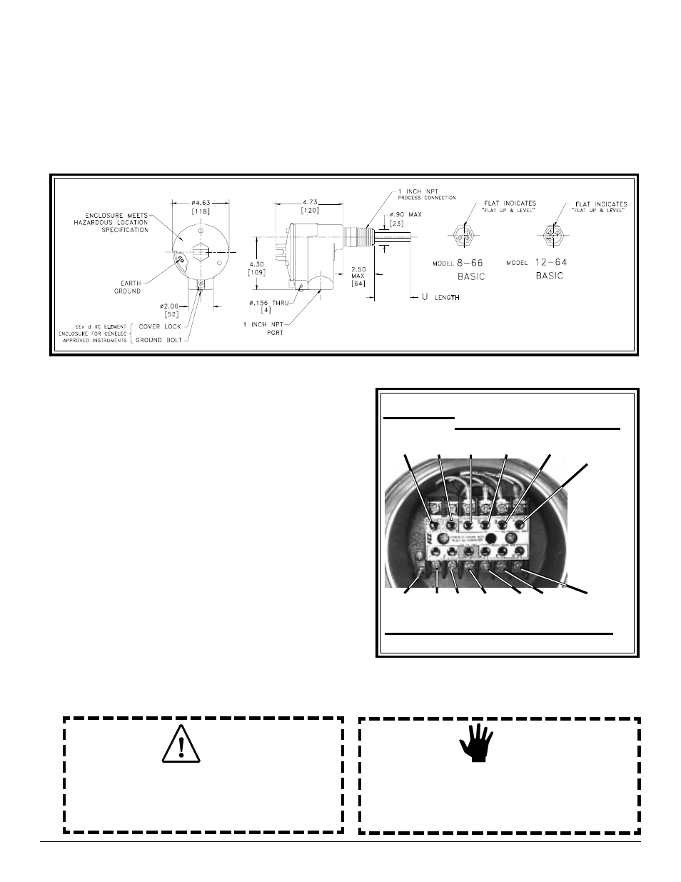
12-64 Flow Switch and 8-66 Level Switch Installation and Outline Drawing
Step 3. Wiring Preparation
Before the instrument is opened to install the wiring, FCI
recommends that the following ESD precautions be
observed: Use a wrist band or heel strap with a
1 megohm resistor connected to ground. If the instrument
is in a shop setting there should be static conductive mats
on the work table and floor with a 1 megohm resistor
connected to ground. Connect the instrument to ground.
Apply antistatic agents such as Static Free made by
Chemtronics (or equivalent) to hand tools to be used on
the instrument. Keep high static producing items away
from the instrument such as non-ESD approved plastic,
tape and packing foam.
The above precautions are minimum requirements to be
used. The complete use of ESD precautions can be found
in the U.S. Department of Defense Handbook 263.
Open the instrument enclosure to wire the instrument.
Remove the control circuit by lifting and rocking the
circuit board back and forth to expose the terminal block
as shown. The wiring connections are then accessible.
12-64/8-66 Wiring Pictorial
SAFETY
GND
COM
ALARM
# 2
PWR PWR
N/O
ALARM
# 1
COM
ALARM
# 1
N/O
ALARM
# 2
N/C
ALARM
# 2
N/C
ALARM
# 1
(HTR 7)
(ACT 7)
(COM 8)
(COM 8)
(REF 9)
(HTR 10)
CUSTOMER
WIRING
FACTORY WIRING
CUSTOMER WIRING
Step 4. Wiring the Instrument
Alert:
The instrument contains electrostatic discharge (ESD)
sensitive devices. Use standard ESD precautions when
handling the control circuit.
Caution:
Only qualified personnel are to wire or test this instrument.
The operator assumes all responsibilities for safe practices
while wiring or troubleshooting.
When mounting the instrument the correct orientation of the flow element must be maintained to ensure repeatability to
within specifications.
Apply sealant to the male threads.
Carefully place in the process media line with the machined flat facing up.
Tighten the process connection. To avoid leaks do not overtighten or cross-thread connections.
Shown below is the 1 inch NPT mounting.
AC or DC
(+) (-)