Rear panel, [dc in] jack, [power] switch – Fostex MR-8 User Manual
Page 14: [usb] port, [foot sw] jack, [digital out] connector, [input a select] switch, Mr-8 owner’s manual
14
MR-8 Owner’s Manual
MIC/LINE
GUITAR
INT MIC
DC IN
POWER
USB
FOOT SW
DIGITAL
OUT
INPUT A SELECT
MIC/LINE
INT MIC
GUITAR
LIGHT
12V
ON
OFF
[NORMAL MODE]
1
2
3
4
5
6
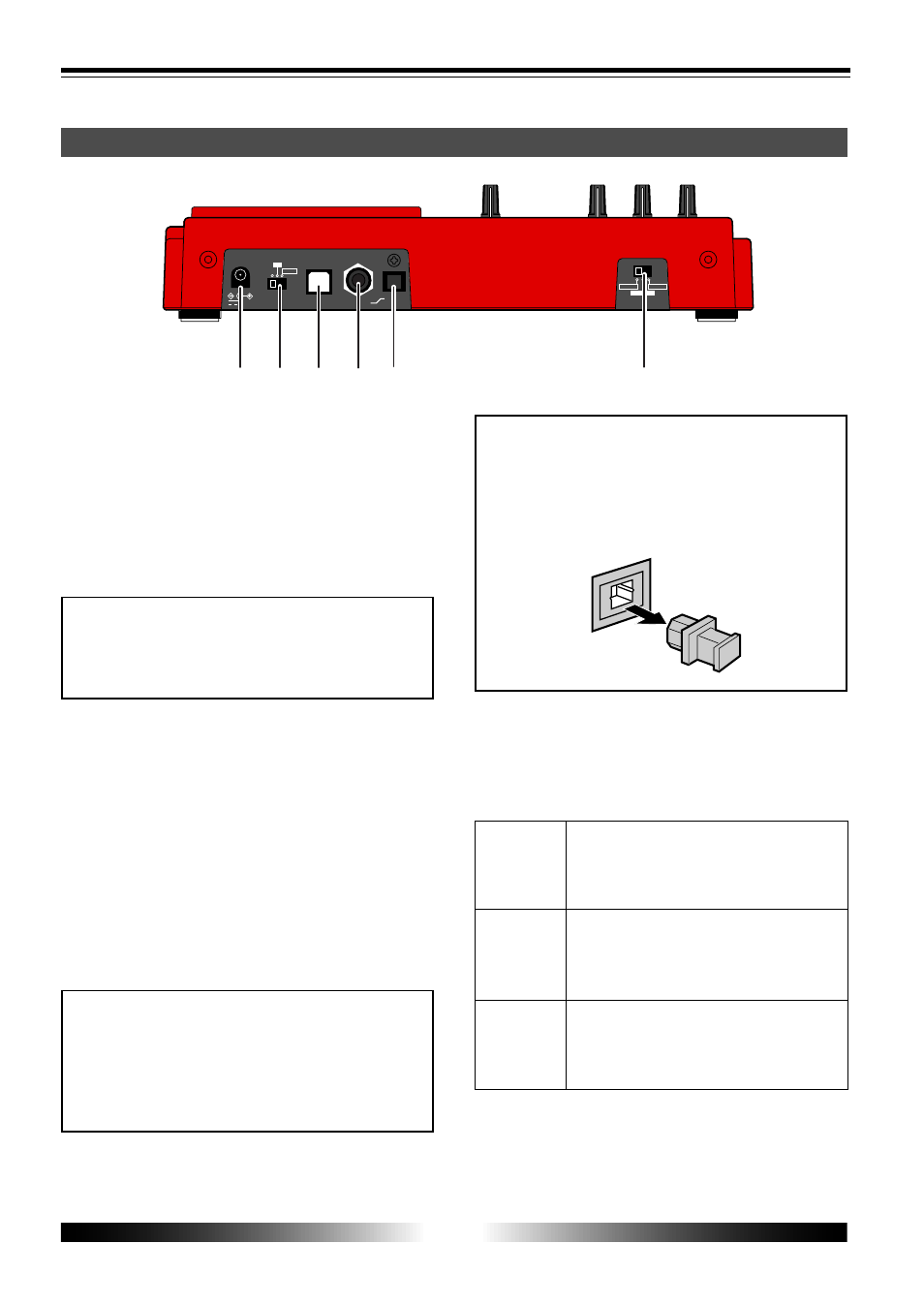
Rear panel
1. [DC IN] jack
Connect the supplied AC adaptor to this jack (see
page 17).
2. [POWER] switch
Used to turn on or off the power.
By setting the switch to "LIGHT", the backlight of
the LCD display lights up (see page 18).
When driving the MR-8 by batteries, we rec-
ommend not to use the backlight, because
the batteries are exhausted quickly.
3. [USB] port
Used to connect with a personal computer using
a standard USB cable (see page 88).
4. [FOOT SW] jack
Used to connect with the optional footswitch
(Model 8051) or an unlatched-type footswitch
(see page 35).
5. [DIGITAL OUT] connector
Used to connect with an external digital device
(see page 48).
Only song data created by the normal mode
(44.1 kHz, 16 bit) can be digitally output from
this port.
Song data created by the extended mode can-
not be digitally output.
6. [INPUT A SELECT] switch
This switch must be set appropriately according
to the input source of the [INPUT A] section (see
page 29).
Set the switch to this position when the source
is an external microphone or line level source.
Both the [BAL] XLR and [UNBAL/GUITAR]
phone connectors can be used.
Set the switch to this position when the source
is a guitar connected to the phone connector.
Both the [BAL] XLR and [UNBAL/GUITAR]
phone connectors can be used.
Set the switch to this position when the source
is the built-in microphone.
Both the [BAL] XLR and [UNBAL/GUITAR]
phone connectors cannot be used.
When you open the MR-8 carton, the protec-
tion cap is inserted to the [DIGITAL OUT] con-
nector. When using the connector, remove
the cap. When no connection is made to the
connector, keep the cap inserted.