Biela14 series gen ii lov, Electric fryers chapter 1: service procedures – Frymaster LOV BIELA14 User Manual
Page 8
1-1
BIELA14 SERIES GEN II LOV™
ELECTRIC FRYERS
CHAPTER 1: SERVICE PROCEDURES
1.1 General
Before performing any maintenance on your Frymaster fryer, disconnect the fryer from the electrical
power supply.
WARNING
To ensure the safe and efficient operation of the fryer and hood, the electrical plug for
the 120-volt line, which powers the hood, must be fully engaged and locked in its pin
and sleeve socket.
When electrical wires are disconnected, it is recommended that they be marked in such a way as to
facilitate re-assembly.
1.2 Replacing a Computer
1. Disconnect the fryer from the electrical power supply.
2. The computer bezel is held in place by tabs at the top and bottom. Slide the metal bezel up to
disengage the lower tabs. Then slide the bezel down to disengage the upper tabs.
3. Remove the two screws from the upper corners of the control panel. The control panel is hinged at
the bottom and will swing open from the top.
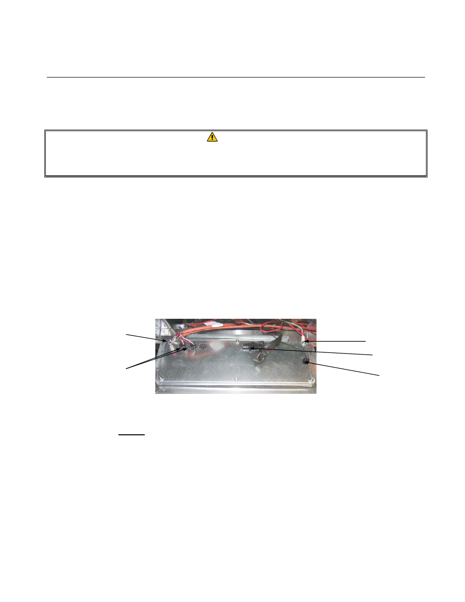
4. Unplug the wiring harnesses from the connectors on the back of the computer, marking their
position for reassembly, and disconnect the grounding wires from the terminals. Remove the
computer panel assembly by lifting it from the hinged slots in the control panel frame.
5. Install the replacement computer. Reinstall the control panel assembly by reversing steps 1 thru 4.
6. Setup the computer following the instructions on page 4-9 in the Installation and Operation
manual. Setup MUST be performed after replacement.
7. Once setup is complete on all replaced computers, reset all control power following the
instructions in section 1.11.7 on page 1-22 to readdress the new M3000 computer. Check software
version and if necessary update the software. If a software update was necessary, follow the
instructions to update the software in section 1.15
1.3 Replacing Component Box Components
1. Disconnect the fryer from the electrical power supply.
2. The computer bezel is held in place by tabs at the top and bottom. Slide the metal bezel up to
disengage the lower tabs. Then slide the bezel down to disengage the upper tabs.
Ground Wire Terminal
20-Pin Connector
Ground Wire Terminal
Communication
Harnesses
Locator Wire