Furuno FSV-84 User Manual
Page 20
1-12
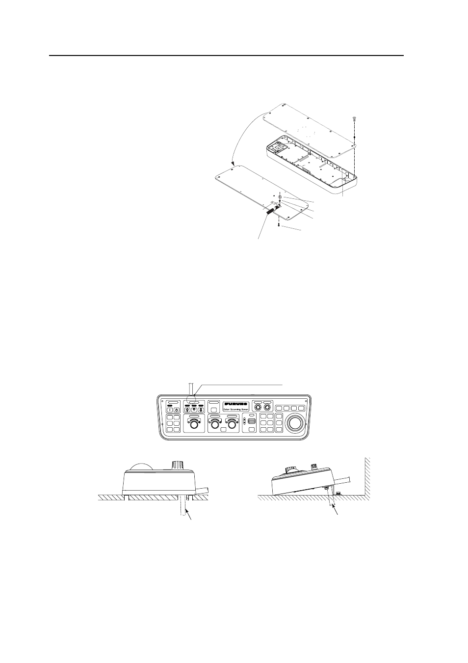
Control unit cover
Previous cable hole
Screw
M4x8 (8 pcs.)
Clamp
Screw (M4x12)
Fasten the cable with the clamp here.
Nut
Spring washer
Flat washer
J1
J2
Control unit, cover removed
Passing the cable through the bottom of the control unit (for permanent mounting)
For permanent mounting methods (2) and (3), the control cable can be passed through the
bottom of the control unit as follows:
1. Unfasten eight screws (M4) to
remove the cover from the bottom
of the control unit.
2. Unscrew two screws (M4
×10) to
remove the cable clamp.
3. Disconnect two connectors J1 and
J2 from the circuit board.
4. Attach the control cable to the
control unit cover with the cable
clamp (removed at step 2), two
flat head screws (M4), flat
washers, spring washers and nuts
(hardware: supplied).
5. Re-connect two connectors
disconnected at step 3.
6. Fasten eight screws to attach the
control unit cover.
7. Attach the connector seal (supplied) to the hole at the rear of the control unit.
8. Drill a hole of 30 mm in diameter to pass the cable from the bottom of the control unit
through the tabletop
9. Attach the connector seal (supplied) to the hole at the bottom of the control unit when the
above modification is not done.
10. Fix the control unit referring to (2) or (3) on the previous page.
Cable
Cable
Without KB fixing plate
With KB fixing plate
Hole for leading in cable
F S V -
8 4
Control unit, side view