Part names and functions (continued) – FUJITSU PLASMAVISION PDS4229W User Manual
Page 9
8
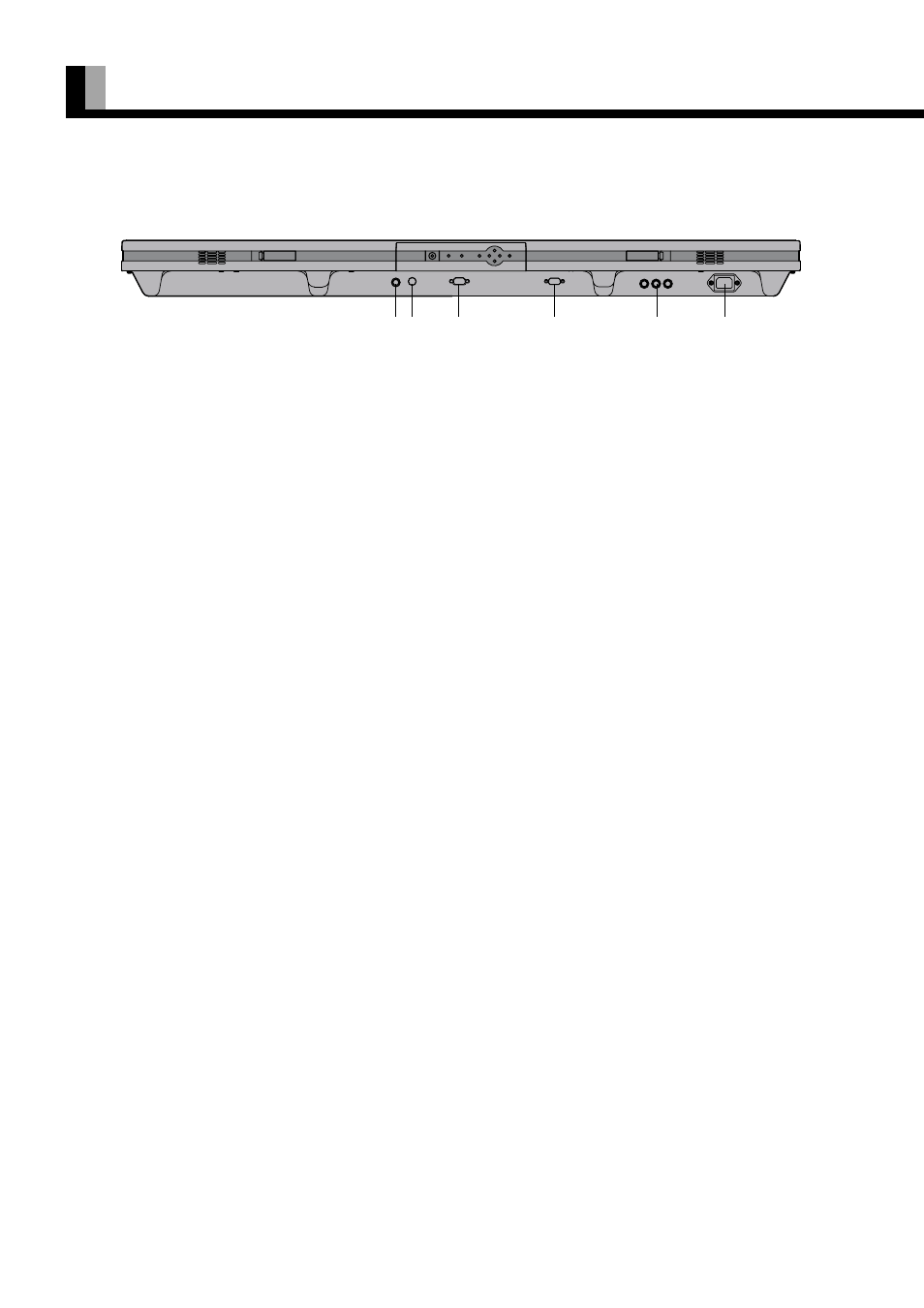
1 Video input terminal (VIDEO INPUT)
Connect this terminal to the video output terminal of your VCR or video disk player.
2 S-video input terminal (S-VIDEO INPUT)
Connect this terminal to the S-video output terminal of your VCR or video disk player.
3 RS-232C terminal (RS-232C)
This terminal is provided for you to control the display from the PC. Connect it to the RS-232C terminal on the PC.
When connecting a cable, attach a ferrite core to the cable. (See P. 12.)
* No RS-232C cable is supplied with the display. The type of cable to be used varies depending on the PC model. Contact your
dealer for more information.
4 RGB input terminal (RGB INPUT/mD-sub)
Connect this terminal to the PC’s display (analog RGB) output terminal or decoder (digital broadcast tuner, etc.) output terminal.
* No RGB cable is supplied with the display. The type of cable to be used varies depending on the PC model. Contact your dealer
for more information.
5 Component video input terminal (COMPONENT VIDEO INPUT)
Connect this terminal to the component video output (color difference output) terminal of your HDTV unit or DVD player.
When connecting a cable, attach a ferrite core to the cable. (See P. 12.)
6 Power input terminal
Connect this terminal to the power cable supplied with the display.
PART NAMES AND FUNCTIONS (Continued)
Bottom
12
3
4
5
6