FUJITSU MAX3073FC User Manual
Page 57
4.1 Mounting Requirements
C141-E234
4-5
(3)
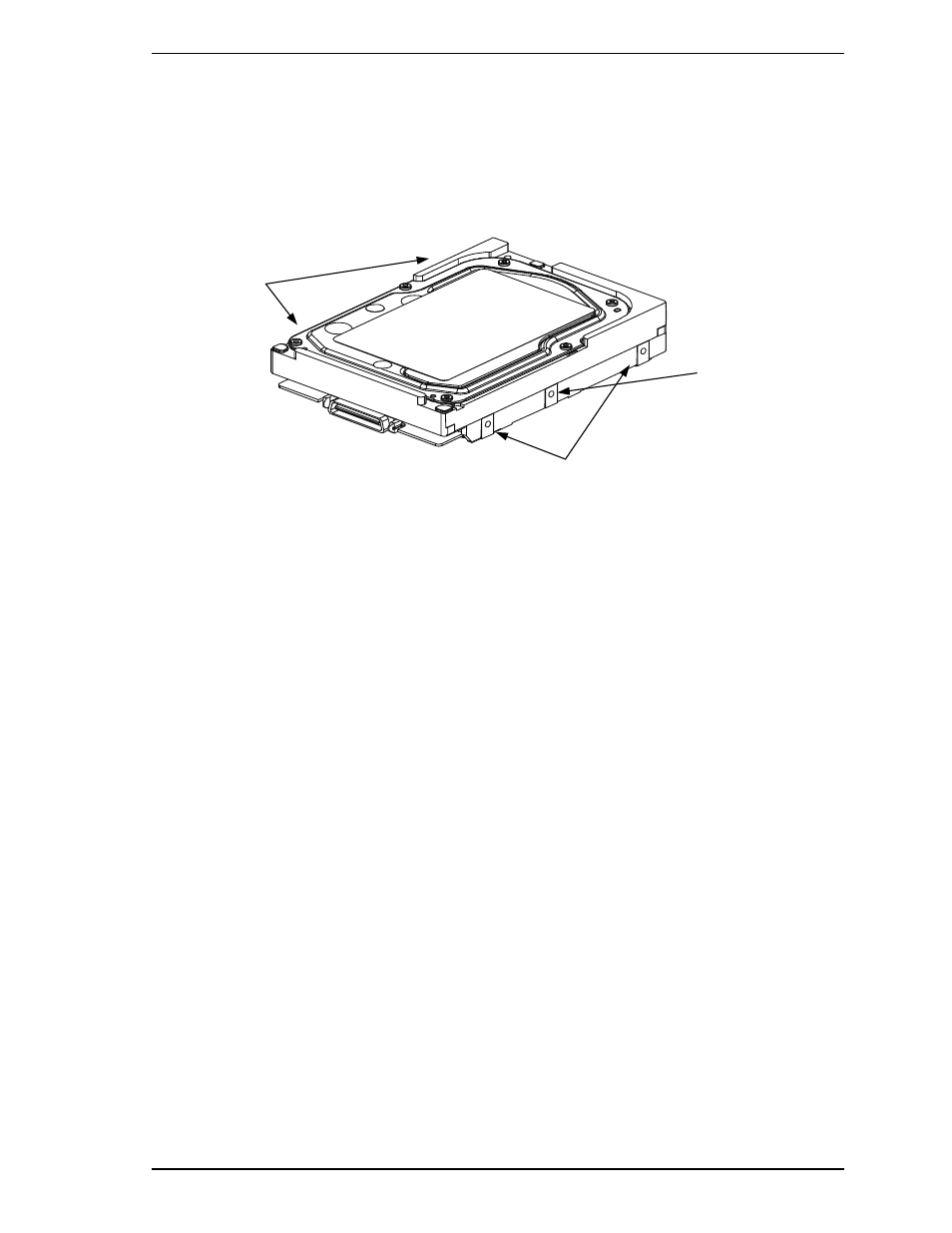
Limitation of side-mounting
Use the four screw holes at the both ends on the both sides as shown in Figure 4.4. Do not use the
center hole by itself.
In case of using the center hole, it must be used in combination with two holes on both ends.
(Total six screws for six holes enclosed)
Holes for
mounting screw
1
2
3
4
In case of using a
center hole, use it in
combination with the
holes of both ends.
Holes for mounting screw
Use four holes (No.1 to No.4) to mount.
Figure 4.4
Limitation of side-mounting
(4)
Limitation of bottom-mounting
Use all four mounting holes on the bottom face.
(5) Environmental
temperature
Temperature condition at installed in a cabinet is indicated with ambient temperature measured
30 mm from the disk drive. At designing the system cabinet, consider following points.
• Make a suitable air flow so that the DE surface temperature never exceed 60°C.
• Cool the PCA side especially with air circulation inside the cabinet. Confirm the cooling effect
by measuring the surface temperature of specific ICs and the DE. These measurement results
must satisfy the temperature condition listed in Table 4.1.
• Keeping the DE surface temperature at 50°C or below at ambient temperature 25°C, which is a
condition for assuring an MTBF of 1,200,000 hours, requires an air flow of 0.8 m/s.