3 system configuration – FUJITSU MAX3073FC User Manual
Page 29
1.3 System Configuration
C141-E234
1-7
1.3 System
Configuration
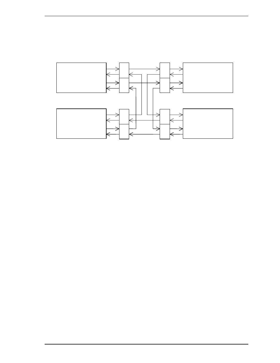
For the Fibre Channel, the ANSI standard defines Arbitrated Loop, Fabric, and Point-to-Point
technologies. The drives support the Arbitrated Loop technology. Figure 1.2 gives an example of
the FC-AL system configuration.
Figure 1.2
Example of FC-AL system configuration
Any device connected to the Fibre Channel is called a node. The nodes shown in Figure 1.2
represent the initiator and individual disk drives. Each node has at least one port called an N_port.
For FC-AL, each port is called a Node-Loop port (NL_port).
The drives have two ports, one of which is used for connections to an FC-AL. A maximum of 126
NL_ports can be connected to a single port.
(1) Loop
configuration
A port embedded with sending and receiving circuits uses differential signals to send and receive data
on electric signal lines. A pair of signal lines is called a link. Since signals are sent in one direction
on a link, the links in a system must be connected to form a loop. The FC-AL interface sends and
receives data via nodes on the loop. Therefore, if a node connected to a loop is powered off or the
interface signals of a node cannot be sent or received correctly, the loop does not work normally. A
common solution preventing this problem from occurring is to add a port bypass circuit on the back
plane of the system. BC in Figure 1.2 indicates the port bypass circuit.
(2) Node
addressing
A specific device number called a SEL ID is assigned to each node on a Fibre Channel loop. The
combination of signal levels on the back plane is used to define the SEL ID of a disk drive. The
signal levels are sent on the seven signals (from SEL_0 to SEL_6) from CN1, which serves as an
SCA interface connector. SEL_6 is the most significant bit (MSB), having a bit weight of the sixth
power of 2, and SEL_0 is the least significant bit (LSB), having a bit weight of the zeroth power of 2.
Any number from 0 (X’00) to 125 (X’7D’) can be assigned as the SEL ID of a disk drive.
BC
Port B
Initiator
(Node-1)
Drive
(Node-4)
BC
Port A
BC
BC
BC
BC
BC
BC
Port B
Port A
Port B
Port A
Port B
Port A
Drive
(Node-2)
Drive
(Node-3)