Generation ii technical reference, Data network flow chart – Frymaster LOV M3000 User Manual
Page 44
LOV
™
Generation II Technical Reference
43
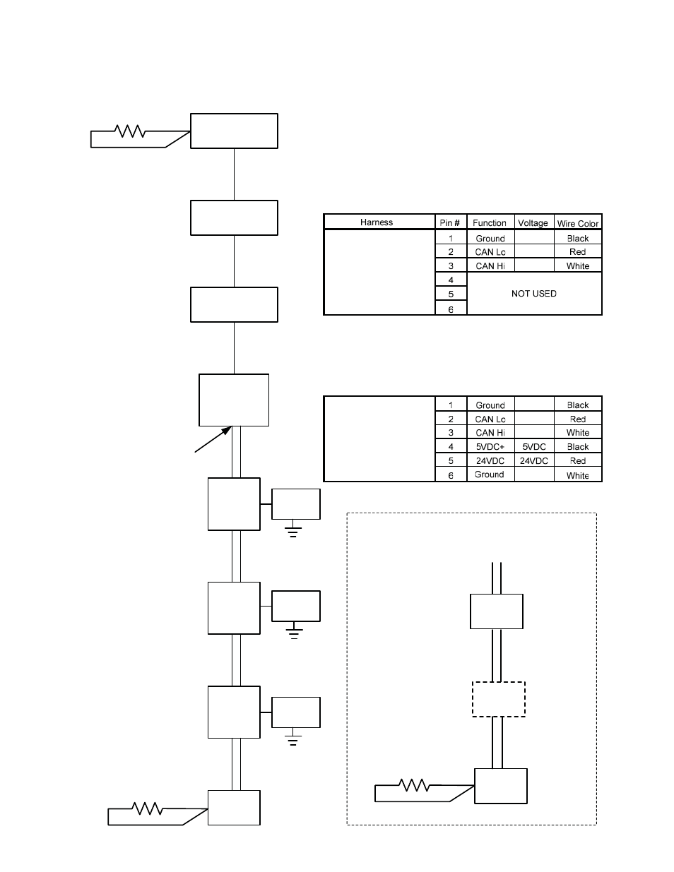
Data Network Flow Chart
Right
M3000
Middle
M3000
Left
M3000
MIB
Left
AIF
Middle
AIF
Right
AIF
ATO
J10
J9
J5
J7
J6
J7
J6
J7
J6
J1
J2
J4
J5
J4
J5
J4
120 Ω Pins 2 & 3
120 Ω Pins 2 & 3
NOTE:
Pins 2 & 3 can
be tested on any plug
throughout the system
and should read 120Ω.
The data network plugs
on the boards can be
swapped. (ie. J4 and
J5 on the AIF board.)
START OF 6-WIRE
DATA AND POWER
(24VDC) HARNESS
3-wire harness
3-wire harness
3-wire harness
6-wire
harness
6-wire harness
3-wire harness
For systems that have a LON Board and/
or 4 or 5 battery systems have an
additional ATO Board.
ATO
J202
J9
120 Ω Pins 2 & 3
6-wire harness
6-wire harness
J10
2
nd
ATO
J9
J10
6-wire harness
LON
J203
2
nd
ATO board only
in 4 and 5 batteries
6-wire
harness
6-wire
harness
6-wire
harness
Oil Level
Sensor
(gas only)
Oil Level
Sensor
(gas only)
Oil Level
Sensor
(gas only)
Turn each computer to OFF. Press the TEMP
button on each computer and verify ALL software
versions are present (M3000, MIB, AIF, ATO and
LON on US only). A missing version may indicate
an open connection. Connections from the MIB to
the AIF boards carry 24VDC on the gray cable.