Firepower, a Thermadyne Company FIREPOWER FP-82 User Manual
Page 42
REPAIRS & REPLACEMENT PROCEDURES
5-10
Manual 0-2871
1) The inner edge of the Panel has tabs that
engage slots in the center chassis. Ensure
that these tabs fully engage in the chassis.
2) Press the Panel downward. Press the bot-
tom flange fully against the bottom panel
of the Power Supply.
3) Ensure that the hole in the bottom flange of
the Fan Shroud engages the mounting stud.
c. Replace nut on the bottom mounting stud.
d. Ensure that top flange of the Fan Shroud is
fully against the top forward edge of the Heat-
sink Shroud.
e. Press the front panel of the Power Supply
against the Fan Shroud, and fasten in place with
the bolt removed previously.
f. Secure the nut on the stud at the bottom of the
Fan Shroud.
9.
Re-connect the wires to the Fan Assemblies.
10. Pass the Work Cable through the hole in the bot-
tom of the Fan Shroud. Ensure that the grommet
is in place in the hole.
11. Connect the Work Cable to terminal E61 on the
Power Output PC Board. Secure the Work Cable
Strain Relief.
12. Re-install the Power Supply Cover.
D. Output Diode PC Board Replacement
Follow the antistatic procedures in subsection 5.02.
NOTE
Follow the electrostatic discharge instructions pro-
vided with the replacement component to prevent
damage to the component.
Thermal pads and the large flat surface on the back
of diodes and IGBTs must be kept clean. Diodes
and IGBTs must not be bent or allowed to pick up
any foreign material. A very clean installation
between the module and the heatsink or chassis is
essential for proper operation.
1.
Remove cover per subsection 5.04-A.
2.
Locate the Output Diode PCB(s) located within the
Output Power PC Board on the Heatsink Shroud.
3.
Carefully remove all wire connections to the Out-
put Diode Board(s).
4.
Remove screw(s) securing Output Diode PC
Board(s) to the Heatsink and remove board(s) from
the Power Supply.
5.
Use isopropyl alcohol to clean the heatsink and
the large flat surface on the back of the replace-
ment component(s). Do not scratch or abrade the
surfaces.
6.
The thermal pad(s), provided with the replacement
part, is a thin metal pad. Remove any loose pro-
tective paper coverings from the pad(s).
NOTE
Protective coverings must be removed from the
thermal pads. Installing thermal pads with pro-
tective coverings in place will cause equipment
damage or failure.
7.
Apply a round thermal pad to the heatsink with a
small piece of light-duty tape. Tape must cover
no more than 1/8” (3 mm) of the edge of the ther-
mal pad. Use the screw hole in the heatsink as a
guide to position the pad.
8.
Secure replacement board as follows:
a. Position the hardware at the bottom of a recess
in the face of the diode. Ensure that the washer
is under the head of the screw(s).
b. Torque hardware to 17 in-lb. (1.9 Nm).
NOTE
Failure to torque properly will cause component
damage.
9.
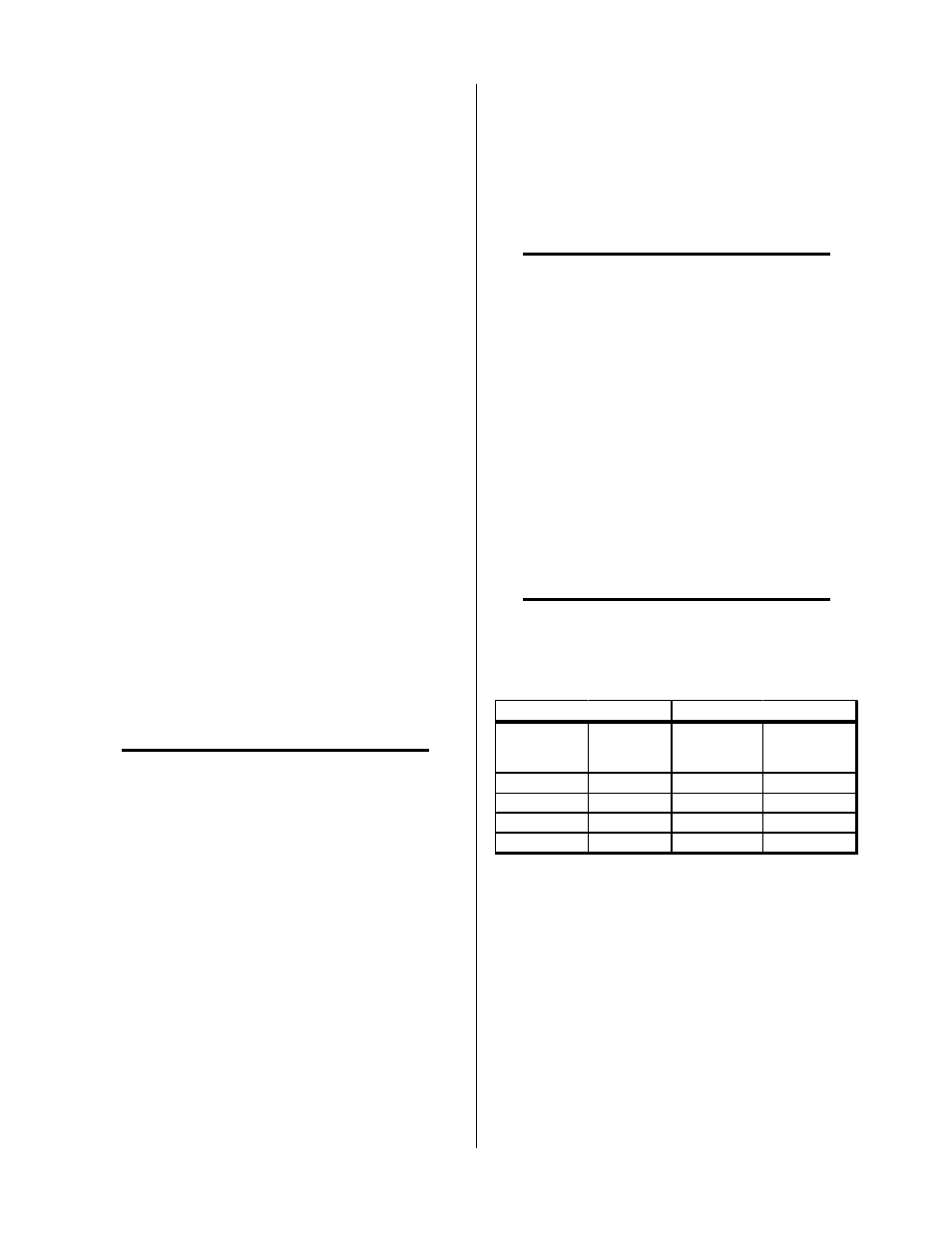
Connect wires as follows:
From Output
Diode A
To Output
Power PCB
From Output
Diode B
To Output
Power PCB
E34, E39
E37
E34, E39
E36
E48, E50
E47
E48, E50
E45
E56, E60
E58
E56, E60
E57
E53, E54
E52
E53, E54
E49
Output Diode A
Output Diode B