Firepower, a Thermadyne Company FIREPOWER FP-82 User Manual
Page 29
Manual 0-2871
4-11
SERVICE
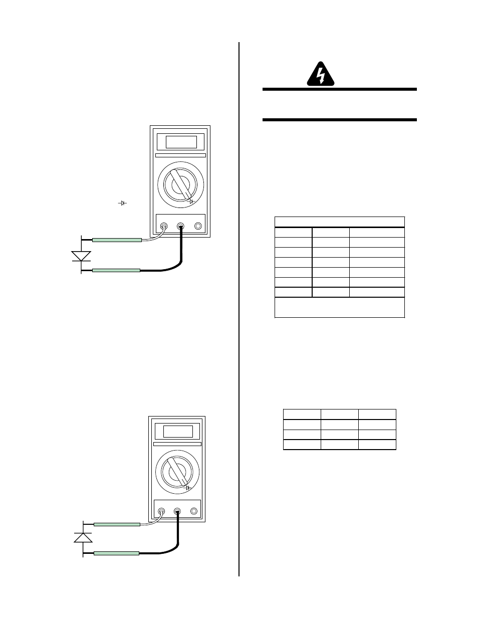
5. Connect the volt/ohmmeter positive lead to the an-
ode (+) of the diode and the negative lead to the cath-
ode (-) of the diode for forward bias testing (refer to
following figure). A properly functioning diode will
conduct in the forward bias direction and indicate be-
tween 0.3 to 0.9 volts.
0.75
VR COM
A
A-00307
Anode
Cathode
Forward Bias
Diode Conducting
+
_
Diode Test Symbol
Testing Diode Forward Bias
6.
Reverse the meter leads across the diode for re-
verse bias testing (refer to following figure). A
properly functioning diode will block in the re-
verse bias direction and depending on the meter
function will indicate an open or “OL”.
7.
If a diode checks bad, replace the diode module.
8.
Reconnect all cables.
OL
VR COM
A
A-00306
Anode
Cathode
Reverse Bias
Diode Not Conducting
+
_
Testing Diode Reverse Bias
C. Diode Module Board Tests
WARNING
Disconnect primary power at the source before tak-
ing any resistance checks.
1. Input Diode Module Board Circuit Test
a.
Remove AC power. Refer to Appendix 5-A or 5-B,
Main Power Wiring diagram.
b. Check Input Diode for shorted input diode. With
an ohmmeter set on the diode range make the fol-
lowing checks from Main PC Board to Input Di-
ode:
Meter (+)
Meter (-)
Indication
E7
E1
Open
E1
E7
Diode Drop
E15
E1
Diode Drop
E1
E15
Open
E15
E7
Diode Drop *
E7
E15
Open
Input Diode PCB
* Indication can be twice
other indications.
c.
The meter should indicate a diode drop in one di-
rection and an open in the other direction for each
check. Replace the Input Diode Module Board if
the readings do not match the chart.
d. If Input Diode Module Board is shorted, make the
following checks with an ohmmeter at the Main
Contactor (W1):
Meter (+)
Meter (-) Indication
L1
T1
Open
L2
T2
Open
L3
T3
Open
If any test has resistance, then replace the Main Con-
tactor.