07 rear panel parts replacement – Firepower, a Thermadyne Company FIREPOWER FP-82 User Manual
Page 38
REPAIRS & REPLACEMENT PROCEDURES
5-6
Manual 0-2871
11. Connect wires per the following applicable
chart(s).
Input Diode
To Main PCB
E18
E3
E13
E2
E5
E1
E14, E16
E15
E6, E8
E7
Firepower 82 Input Diode Connections
IGBT A
Connector
To Main PCB
Connector
IGBT B
Connector
To Main PCB
Connector
J3
J25
J3
J31
J7
J30
J7
J26
E9, E11
E10
E9, E11
E27
E19, E21
E20
E19, E21
E30
E12, E17
E4
E12, E17
E23
IGBT A
IGBT B
Firepower 82 IGBT Connections
12. Stand the unit upright; reinstall the cover.
E. Main Power PC Board Replacement
Follow the antistatic procedures in subsection 5.02.
1.
Remove cover per subsection 5.04-A.
2.
Remove the Logic PC Board per subsection 5.06-C.
3.
Label and disconnect all wire and cable connec-
tions to the Main PC Board. Refer to the Main PC
Board Wiring Diagrams in the Appendix Pages if
necessary. Straighten the connections to the
smaller PC Boards to be perpendicular to the Main
PC Board.
4.
Remove the two long Transformer screws secur-
ing the Transformer to the Center Chassis.
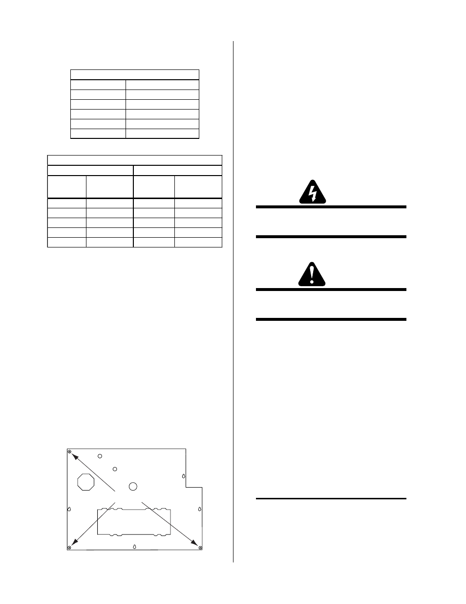
5.
Remove the other screws securing the PC Board
to the Center Chassis.
A-03165
Screw locations
6.
Remove the Logic Board standoffs.
7
.
Carefully remove the original PC Board from the
unit.
8.
Install the replacement PC Board by reversing the
steps above. It may be easier to install the PC Board
if the Power Supply is turned on its right side first.
Refer to the charts in subsection 5.06-D for input
diode and IGBT wiring connection points.
5.07 Rear Panel Parts Replacement
Refer to subsection 6.02 for parts list and overall detailed
drawing.
WARNING
Disconnect primary power from the source before
opening or disassembling the power supply.
A. Filter/Regulator Assembly Replacement
WARNING
Disconnect the gas supply at the source and bleed
down the system before attempting this procedure.
1.
Disconnect the gas input hose from the Filter/
Regulator Assembly on the Rear Panel of the unit.
2.
Remove the four bolts securing the
Regulator
Mounting Bracket to the Rear Panel.
3.
Disconnect the black gas tube from the Filter/
Regulator Assembly Adapter Fitting. Hold a
wrench or similar tool against the
locking ring on
the Fitting and pull on the tube to release it.
4.
Remove the nut securing the Filter/Regulator As-
sembly to the Regulator Mounting Bracket. Re-
move the Filter-Regulator Assembly from the
Mounting Bracket.
5.
Transfer the pressure gauge from the original Fil-
ter/ Regulator Assembly to the replacement as-
sembly.
NOTE
For a secure seal, apply thread sealant to the fit-
ting threads, according to manufacturer's instruc-
tions. Do Not use Teflon tape as a thread sealer as
small particles of the tape may break off and block
the small gas passages in the torch.