09 main arc problems – Firepower, a Thermadyne Company FIREPOWER FP-82 User Manual
Page 27
Manual 0-2871
4-9
SERVICE
C. Gas flows; No arc in torch; No arc at spark gap on
CD PC Board; AC indicator ON; TEMP indicator
off; GAS and DC indicators ON; CD enable
indicator ON
1. Faulty IGBT
a. Measure between the following points on the
IGBTs: (Refer to Appendix 4)
• IGBT A:
E4 to E10
E10 to E20
•IGBT B:
E23 to E27
E27 to E30
Voltage should be approximately 20 vdc before
the start signal is active. If voltage measures
approximately 440 vdc when the start signal is
active, replace the respective IGBT(s).
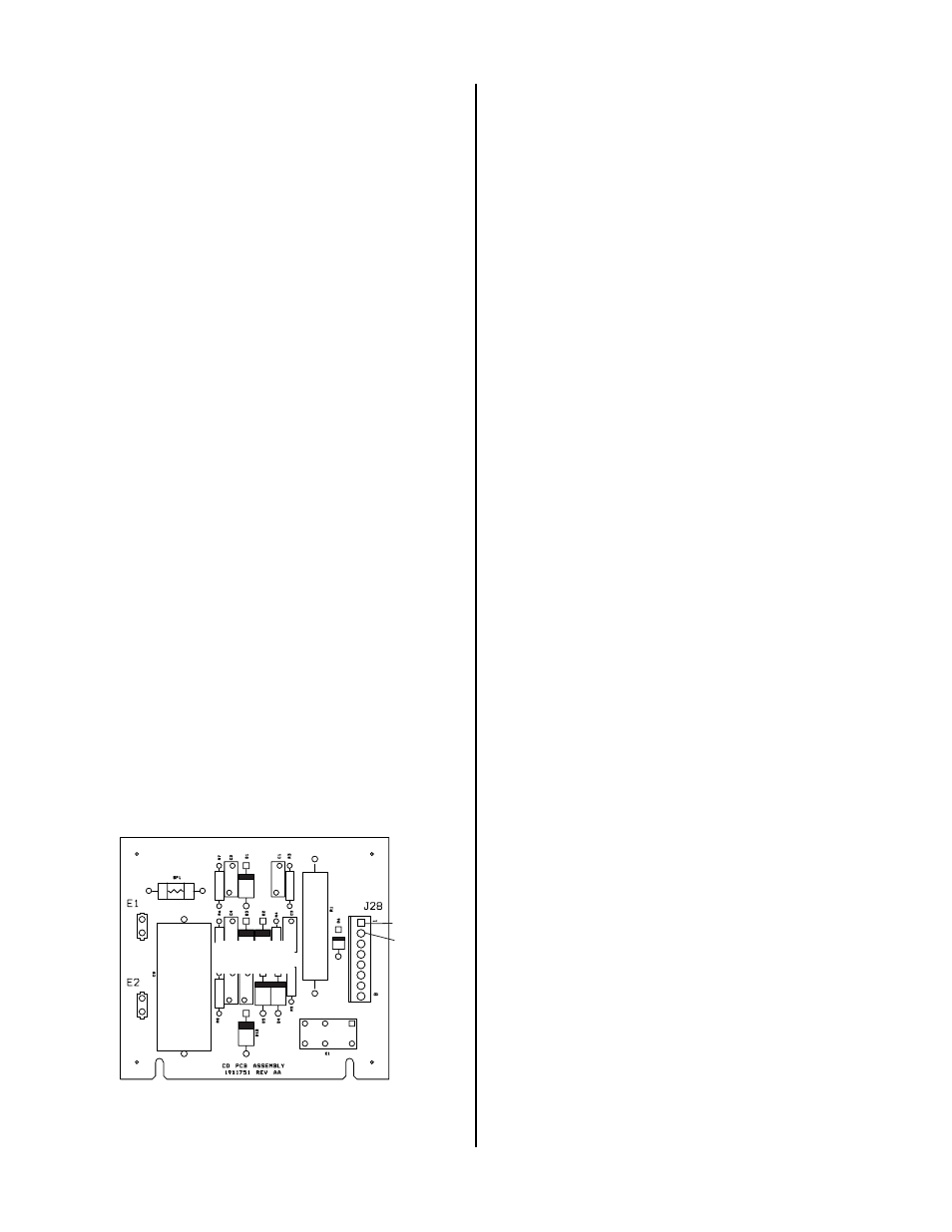
2. Faulty CD PC Board. (Refer to Appendix 6, CD Board
Layout)
a. Measure for approximately 12 vdc at J28-1 to
TP-6 (on Main PC Board) when the torch is ac-
tivated. Measure for less than 2 vdc at J28-2 to
TP6 (on Main PC Board).
• Check for approximately 250 VAC between pin
J28-5 and J28-8 on CD PC Board.
• If voltages are not present, check all wiring and
connections. If wiring is connected properly
and is not shorted, replace the main trans-
former.
b. Check for OCV at E61 to E64 on Power Output
PC Board.
• If voltage is present, and the other measure-
ments above are correct, replace CD Board.
A-03175
J28-1
J28-2
CD PCB
D. No arc or intermittent arc in torch; Gas flows;
Spark at gap on CD PC Board; AC indicator ON;
TEMP indicator off; GAS and DC indicators ON;
and CD enable indicator ON
1. Gas pressure set incorrectly (too high)
a. Refer to appropriate Torch Instruction Manual.
2. Oil/moisture in air lines
a. Purge system. If problem corrected, add filters
in line with air source.
3. Incorrect torch parts
a. Refer to appropriate Torch Instruction Manual.
4. Faulty leads
a. Check continuity per appropriate Torch Instruc-
tion Manual.
5. Faulty torch
a. Check continuity per Torch Instruction Manual.
6. Faulty connection of wire #58 or 62 to Main PC Board
a. Check wiring connection. Refer to the appro-
priate System Schematic in the Appendix.
7. Faulty Main PC Board
a. Check for approximately 12 vdc at TP2 to TP1.
If less than 2 vdc, replace the Main PC Board.
8. Faulty Logic PCB or Faulty PCR Relay
a. Visually check that the pilot control relay (PCR)
is closed. If not, check for approximately 12
vdc across the coil.
• If approximately 12 vdc is present, replace
the relay.
• If there is no 12 vdc across the coil, replace
the logic board.
b. Install a jumper between wires 58 and 62 on
PCR relay and retry piloting. If torch pilots with
jumper installed, replace PCR Relay.