Firepower, a Thermadyne Company FIREPOWER FP-82 User Manual
Page 30
SERVICE
4-12
Manual 0-2871
2. Output Diode Module Board Circuit Test
a.
Use an ohmmeter set on the diode function and
make the following measurements on the Output
Diode Module Boards to Power Output PC Board.
Indication
Meter +
Meter - Meter + Meter -
E37
E58
E36
E57
Diode Drop *
E58
E37
E57
E36
Open
E37
E47
E36
E49
Diode Drop
E47
E37
E49
E36
Open
E58
E47
E57
E49
Open
E47
E58
E49
E57
Diode Drop
Output Diode A
Output Diode B
* Indication can be twice other indications.
b. The meter should indicate a diode drop in one di-
rection and an open in the other direction for each
check. Replace the Output Diode Module Board(s)
if the readings do not match the chart.
3. IGBT Module Board Circuit Test
a.
Use an ohmmeter set on the diode function and
make the following measurements on the IGBT
Module Board(s) to the Main PC Board.
Indication
Meter + Meter - Meter + Meter -
E10
E4
E27
E23
Diode Drop
E4
E10
E23
E27
Open
E10
E20
E27
E30
Open
E20
E10
E30
E27
Diode Drop
E4
E20
E23
E30
Open
E20
E4
E30
E23
Diode Drop *
IGBT PCB A
IGBT PCB B
* Indication can be twice other indications.
b. The meter should indicate a diode drop in one di-
rection and an open in the other direction for each
check. Replace IGBT Module Board(s) if readings
are not the same as the chart.
D. Main Input Power Test
WARNING
The following tests must be performed with the
power supply connected to primary input power.
There are extremely dangerous voltage and power
levels present inside this unit. Do not attempt to
diagnose or repair without proper training in power
electronics measurement and troubleshooting tech-
niques.
Reconnect power and observe proper start-up procedure.
AC LED Indicator on the Front Panel should be ON. If
indicator is OFF there is no voltage to the Power Supply
or an overvoltage condition exists.
1.
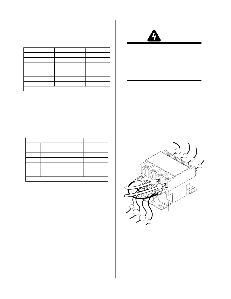
If AC LED Indicator on Front Panel is OFF, check
for proper AC input voltage between input cables
on the Main Contactor. Input voltage should be
187-253VAC between contactor points L1 and L2.
If not, check for proper voltage at the main power
source.
A-03212
L1 L2 L3 L4
T1 T2 T3 T4
#4
#13
#12
#5
#1
#3
#2
#78
L1
L2
Input
Side
Main Input Contactor
2.
Check for 28 VAC at J23-1 to J23-3 on the Main PC
Board.
a. If greater than 30 VAC, input line power is too
high.
b. If there is no AC power, check the fuse. If the
fuse is ok, the auxiliary transformer is faulty.
Replace the Main PC Board.