06 circuit fault isolation – Firepower, a Thermadyne Company FIREPOWER FP-82 User Manual
Page 22
SERVICE
4-4
Manual 0-2871
4.06 Circuit Fault Isolation
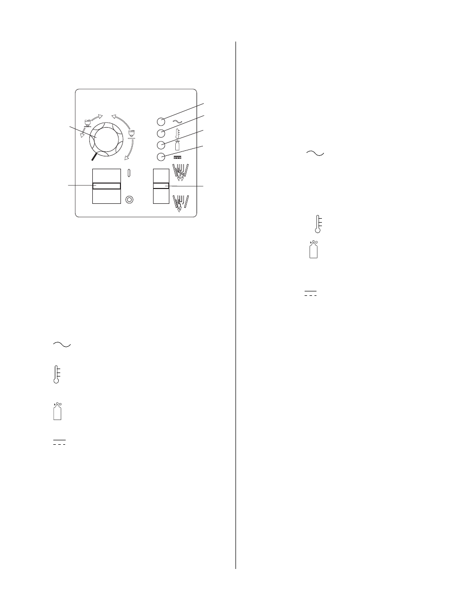
A. Controls and Indicators
A-03208
A
1
4
5
6
7
2
3
20
40
60
1. ON/OFF switch. This switch controls AC power to
unit. Up is ON, down is OFF.
2. RUN/SET switch. This switch controls gas to torch.
Up is RUN, for general torch operation. Down is SET,
for setting gas pressure and purging lines.
3. Current control knob. This control regulates current
to torch. At output settings over 40 amps, circuitry in
the power supply automatically reduces output cur-
rent to 40 amps if the torch tip contacts the workpiece.
4.
AC indicator.
When lit, indicates operating
power is present in the unit.
5.
TEMP indicator.
Indicator comes on when inter-
nal sensors detect temperatures above normal limits.
6.
GAS indicator.
Indicates adequate supply pres-
sure is present in the unit.
7.
DC indicator.
Indicates DC power output cir-
cuit is active. (Torch must be activated).
B. Initial Setup Conditions
This section is to help isolate the defective circuit before
troubleshooting, identify symptoms, and test the unit for
proper operation. Follow the instructions as given to iden-
tify the possible symptom(s) and the defective circuit.
After repairs are complete, run the following tests again
to verify that the unit is fully operational.
1. Connect gas supply to rear of Power Supply.
2. Turn on gas supply and adjust Power Supply Gas
Regulator to 70 psi (4.8 bar).
3. Set the Power Supply controls as follows:
• ON/OFF switch to OFF (Down)
• RUN/SET switch to SET (Down)
• CURRENT control (A) to maximum
C. Main Input and Internal Power Tests
1. Connect main AC power to the unit.
2. Set the Power Supply ON/OFF switch to ON (up) and
note the following:
• AC indicator
blinks for eight seconds (ap-
proximately), then steady ON
• Relay K4 on Main PC Board energizes (clicks) while
AC indicator is blinking
• Relay K5 energizes pulling in W1 after AC light
stops blinking.
• TEMP Indicator OFF
• GAS Indicator
ON
• Gas flows
• Fans operate
• DC lndicator
is OFF
3. Set the Power Supply RUN/SET switch to the RUN
(up) position and note the following:
• GAS indicator goes OFF
• Gas flow stops
This completes the Main Input and Internal Power Tests.
If the above are all correct then proceed to paragraph 'D'.
If not, note the symptom and proceed to Subsection 4.07,
Main Input and Internal Power Problems.
D. Pilot Arc Test
1. Activate the torch to establish a pilot arc and note the
following:
• Gas flows
• GAS indicator turns ON
• Preflow delay (two seconds) then DC indicator turns
ON
• Pilot arc established
This completes the Pilot Arc Test. If the above are all cor-
rect then proceed to paragraph 'E'. If the unit does not
function properly, then note the symptom and proceed
to Subsection 4.08, Pilot Arc Problems.