7 operation, 1 messages, 2 display elements – Pilz PSSu E S 2AI RTD User Manual
Page 32: 1 display elements for module diagnostics, Section 7, Operation, Messages, Display elements, Display elements for module diagnostics, 7operation
Operation
Operating Manual PSSu E S 2AI RTD(T)
22017EN06
32
7
Operation
7.1
Messages
An error will be signalled to the head module and will be entered in the head module's error
stack. A module error will also be displayed via the "Err" LED (see section entitled "Display
elements").
The module can detect the following errors:
Errors
Explanation
Remedy
Startup error
Error as the PSSu system starts
up
Change faulty module.
Configuration error
Incorrect module type configured.
The configured hardware registry
does not match the actual hard
ware registry.
ST communication error
Error during ST communication
Change faulty module.
Bus termination error
There is no terminating plate or
there is a bad contact with the
module bus.
Install a terminating plate with in
tegrated end bracket or insert the
base modules together correctly.
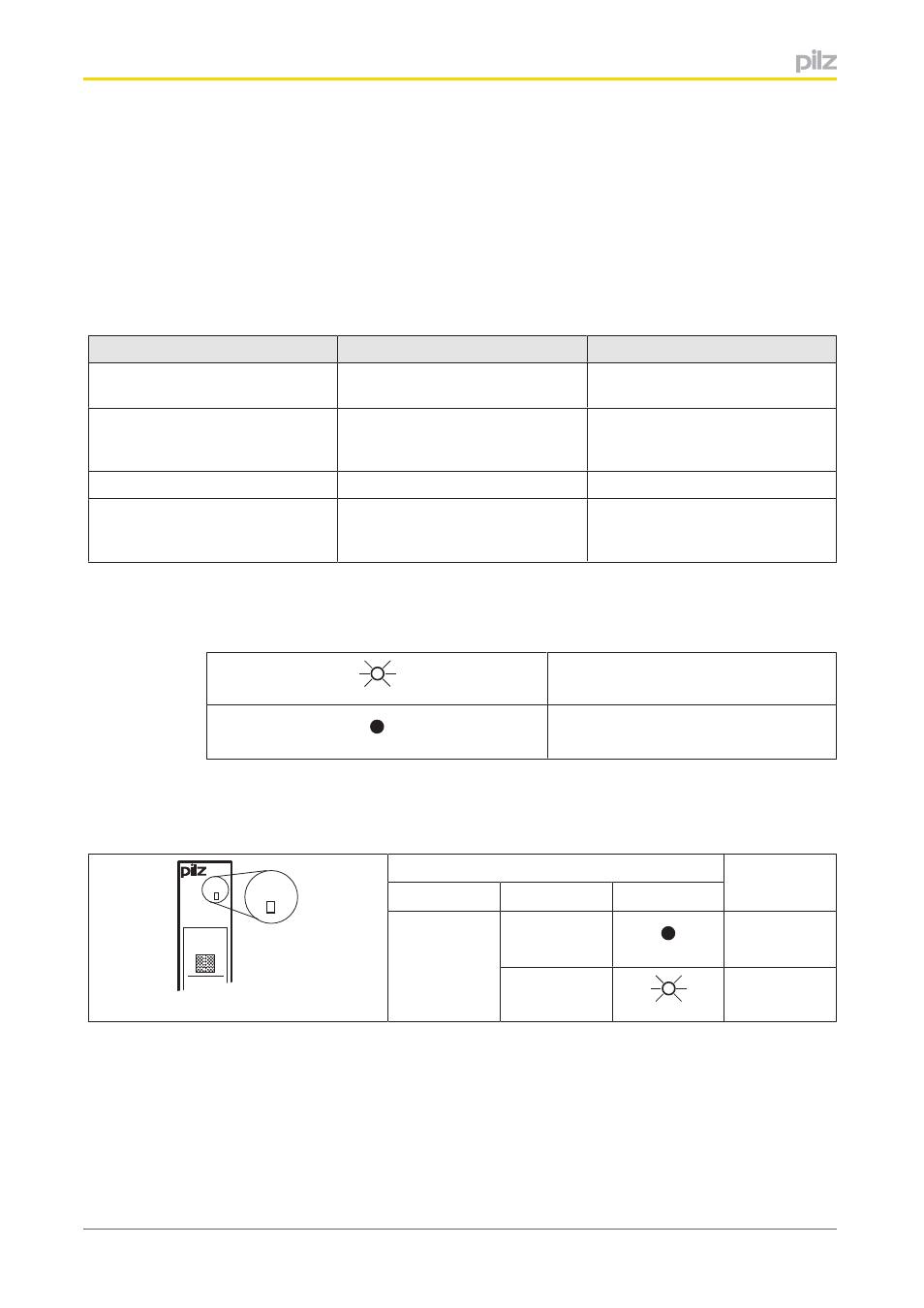
7.2
Display elements
Legend:
LED on
LED off
7.2.1
Display elements for module diagnostics
The module has an LED for displaying module errors ("Err" LED).
Err
11
I0
21
I1
Err
LED
Meaning
Designation
Colour
Status
Err
No error
Red
Module is
faulty