9 pssu assignment in system environment a, 1 status byte, Pssu assignment in system environment a – Pilz PSSu E S 2AI RTD User Manual
Page 20: Status byte
Function description
Operating Manual PSSu E S 2AI RTD(T)
22017EN06
20
4.2.9
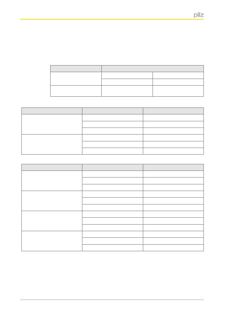
PSSu assignment in system environment A
Each input occupies 16 consecutive bit addresses for the input data. Each input occupies
an additional 8 consecutive bit addresses for the status byte, where this has been con
figured for the input. All the status bytes are displayed first in the PII, followed by the input
data.
Configuration
Standard bus system
Input data
STPII
STPIO
32 Bit
Input data and status byte
("X")
48 Bit
Bit sequence in the PII, input data only, no status byte:
Input
PII
Assignment
Input I0
1
LSB input data
...
...
16
MSB input data
Input I1
17
LSB input data
...
...
32
MSB input data
Bit sequence in the PII, input data and status byte:
Input
PII
Assignment
Input I0
1
LSB status byte
...
...
8
MSB status byte
Input I1
9
LSB status byte
...
...
16
MSB status byte
Input I0
17
LSB input data
...
...
32
MSB input data
Input I1
33
LSB input data
...
...
48
MSB input data
4.2.9.1
Status byte
ST modules for measuring temperature can transfer a variety of status information to the
STPII (see table below for the conveyed status). The information is transmitted using the
input's status byte. Read access (R) is configured for the input for that purpose.