5 digital filter, 6 scaling, Digital filter – Pilz PSSu E S 2AI RTD User Manual
Page 15: Scaling
Function description
Operating Manual PSSu E S 2AI RTD(T)
22017EN06
15
}
Enter the measuring line resistance (feed and return line) in 1/16 Ohm under "2wire
measurement offset".
–
When you have established the measuring line resistance using the module, rese
lect the required sensor under "Measuring range".
4.2.5
Digital filter
A digital filter suppresses interference frequencies in the input signals. The module's pro
cessing time will vary depending on the filter. With 3wire measurement, or when a sensor
with four wires is connected, the filter time is double that found with a 2wire measurement.
The module's processing time corresponds approximately to the sum of the filter times of
both inputs.
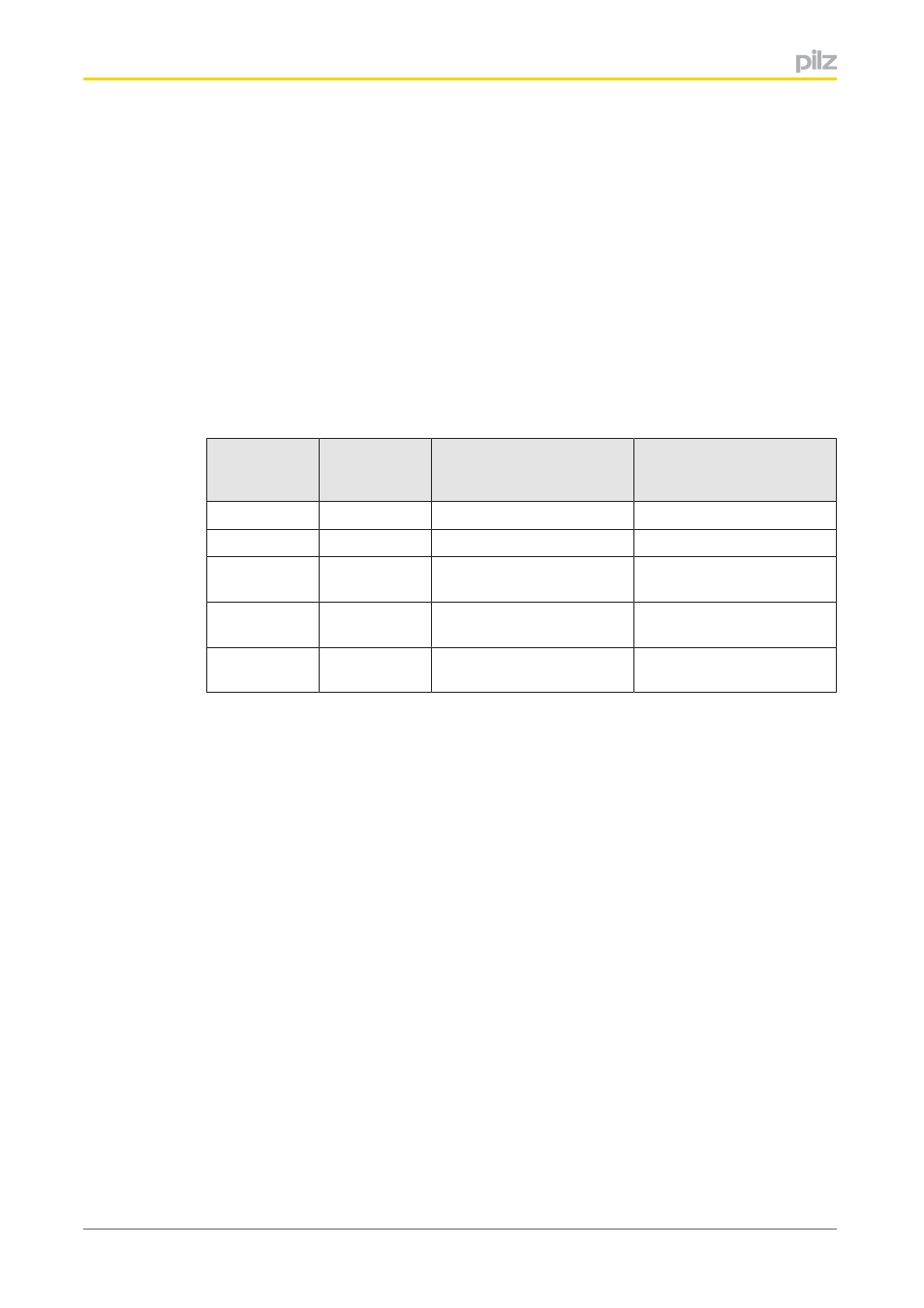
You can select one of the following filters per input:
Filtered
frequencies
Attenuation
Filter time per input
2wire measurement
Filter time per input
3wire measurement
4wire sensor connection
60 Hz
90 dB
103 ms
206 ms
50 Hz
80 dB
122 ms
244 ms
50 Hz and 60
Hz
65 dB
122 ms
244 ms
50 Hz and 60
Hz
69 dB
202 ms
404 ms
50 Hz and 60
Hz
74 dB
482 ms
964 ms
4.2.6
Scaling
Scaling is a multistage process to adapt the values from the AD converter. The straight
path in the diagram indicates the default configuration.