1 listener input program message format, Sens : tel : rang ui4, Sens : tel : brat m9953 – Anritsu MP1777A User Manual
Page 29: Sens : tel : brat, 1 listener input program message format -2
Attention! The text in this document has been recognized automatically. To view the original document, you can use the "Original mode".
3.1
Listener Input Program Message Format
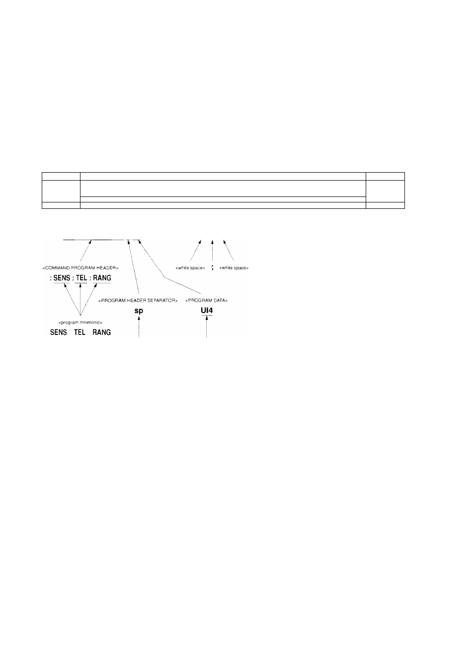
The following section shows program messages when, for example, 4 UI is selected for the reception jitter and the
reception signal is set to 9953M.
Section 3 Listener Input Format
Address 3
Listener address specification
A' '' '
V ^
Listener
(device)
/
(
WRITE (0)03
:
SENS
:
TEL
;
RANG UI4
; ;
SENS
;
TEL
;
BRAT M9953"
Talker
(controller)
\
/ /
V V
N /' / '\ '\
: SENS : TEL : RANG UI4
sp ; sp SP ; SENS : TEL : BRAT M9953^, \ \ \ NL : SENS : TEL : BRAT SEPARATOR> UI4 The program message format comprises a sequence of functional elements divided into the units of minimum level to express functions. The uppercase letters in angled brackets ( < and > ) in the figure above show examples of functional elements. The functional elements are further divided into elements called the coding elements. The lowercase letters in angled brackets ( < and > ) in the figure above show examples of coding elements. The following pages provide explanations of the program message format using the functional syntax diagram and coding syntax diagram. • Functional syntax diagram: Graphic representation of selection of functional elements along specific routes • Coding syntax diagram: Graphic representation of selection of coding elements along specific routes 3-2 Artisan Technology Group - Quality Instrumentation ... Guaranteed | (888) 88-SOUR