Reference photo for assembly and instructions – Craftsman 247.88110 User Manual
Page 4
Attention! The text in this document has been recognized automatically. To view the original document, you can use the "Original mode".
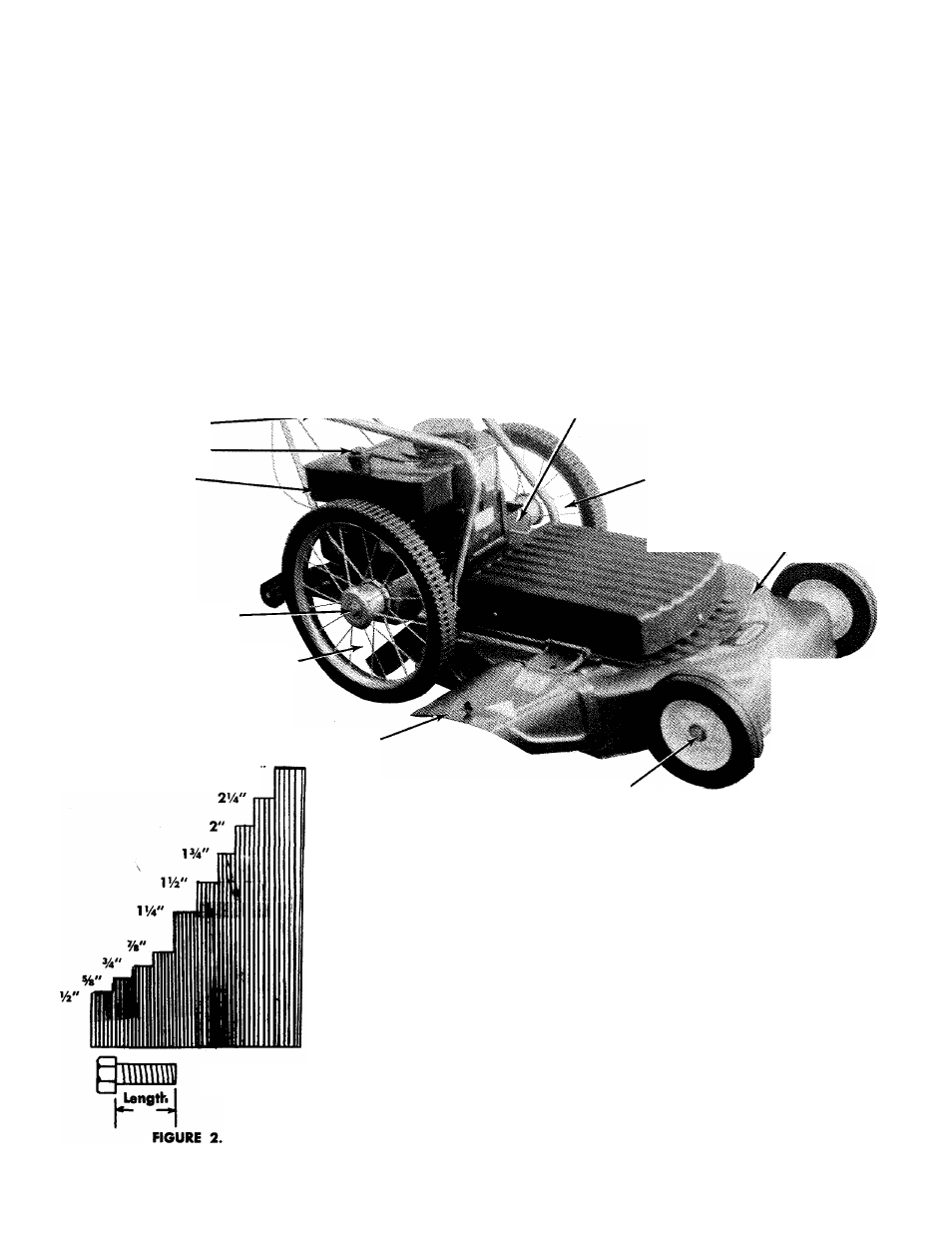
REFERENCE PHOTO FOR ASSEMBLY AND INSTRUCTIONS
Upper Handle (2)
Throttle Control
L
K;-
/
Blade Engaging
Lever (Under Handle ',
Panel)
Throttle Control Cable.
Grips (2)
Handle Panel
Lower Handle (One Piece)
L. H Brace
/ X-
R.H. Brace
Gasoline Filler Cap
Gasoline Tank
Starter Handle
Oil Fill and Drain Left Side of Engine
Rear Wheel Assembly
Rear Wheel Axle Bolt
Rear Protective Shield Assembly
Shroud
Deck Assembly
Chute Deflector Assembly
2'/2
Front Wheel Axle Bolt'
Front Wheel Assembly
Length
Measure Screws Here
LIST OF CONTENTS IN HARDWARE PACK
(11) He.-: Center Locknuts 14-20 Thread.
(3) He>, Head Bolts 14-20 Thread x 114" Long.
(3) Hex Head Bolts 14-20 Thread xl Vi" Long.
(2) Hex Head Bolts V4-20 Thread x 2Vi" Long.
(2) Slotted Hex Head Screws 8-32 Thread x Vi" Long,
n) Speed Nut.
(1) Truss Head Machine Screw 10-24 Thread x %"
Lonn
(1) Hex I'-ad Bolt %-16 Thread x 1" Long.
(1) Hex head Bolt %-16 Thread x %" Long.
(2) Flat Washers %" I.D.xl54" O.D. x 5/32 Thick.
(1) Flat Washer V4" I.D. x’/
2
" O.D. x 1/16" Thick
(1) Flat Washer Vi" l.D. x O.D. x 1/32" Thick.
Refer to figure 4.