Connect the mast assembly to the frame assembly, Caution – Wheatheart S2000 Post Pounder User Manual
Page 23
W
HEATHEART
- P
OST
P
OUNDER
3. A
SSEMBLY
S2000 M
ODEL
3.2. A
SSEMBLING
THE
S2000 P
OST
P
OUNDER
IM15 R1
23
2. Connect the jack stands to the frame assembly, and secure the jack stands
using the supplied lock pins and hair pins.
3. Remove the temporary supports from the assembly, and adjust the jack
stand legs until the frame assembly is level.
3.2.2. C
ONNECT
THE
M
AST
A
SSEMBLY
TO
THE
F
RAME
A
SSEMBLY
1. Position the mast assembly with the ballast box facing upward on a surface
that will protect the back of the assembly from abrasion (e.g. plywood, wood
support blocks, or the bottom of the assembly’s shipping crate).
2. Secure a sling around the centre of the angle iron hammer stop at top of
mast assembly, and attach the sling to a lifting device.
Figure 3.2 Lifting Sling Attachment Point
3. Slowly lift the mast assembly into an upright position, then raise or lower it
over the frame assembly until the four mast assembly bolt holes (located on
tabs on the back of the assembly) are as closely aligned with the four bolt
holes on the pivot arm as possible.
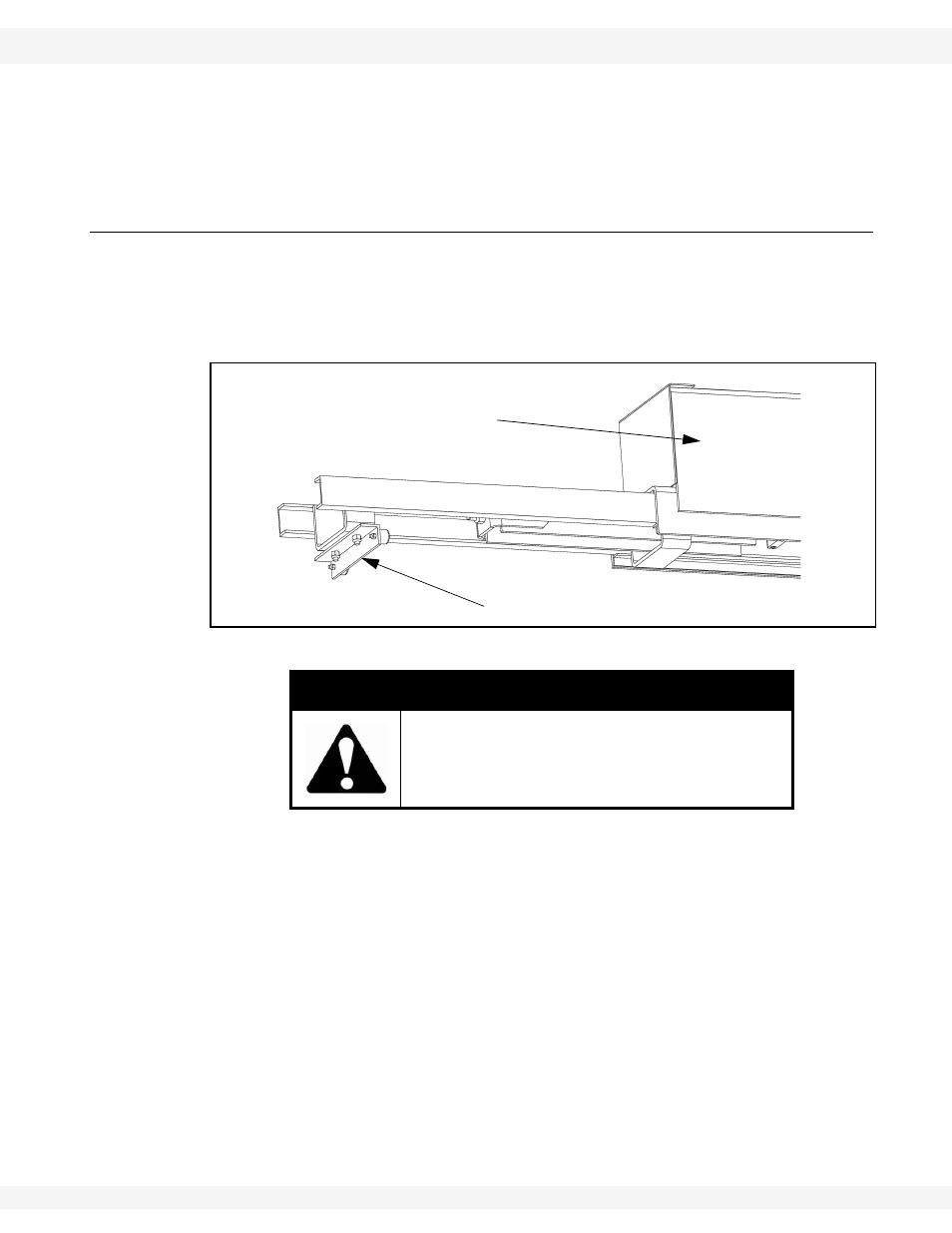
4. Connect the mast assembly to the frame assembly using 5/8” x 2” fine-thread
bolts through each bolt hole and secure with 5/8” fine-thread locknuts (see
Figure 3.3). Further alignment of the bolt holes may require very small
adjustments to the height of the mast assembly, or adjustments to the
position of the frame assembly. A pry bar and mallet may be required to
adjust the two assemblies into proper position.
CAUTION
Secure sling only around the angle iron
hammer stop. Securing at another point could
cause mast to slide when lifted, potentially
damaging equipment or causing injury.
SECURE SLING TO ANGLE IRON HAMMER STOP
BALLAST BOX