Figure 3-4: relay assembly power connection, 4 driver module, Figure 3-5: driver module layout – Hale AutoFill-E Tank Refill Control System User Manual
Page 17: Installation - continued, Driver module
17
AUTOFIll-E Installer / User Guide
p/n: 029-0020-81-0
Installer Installation and Calibration
❑
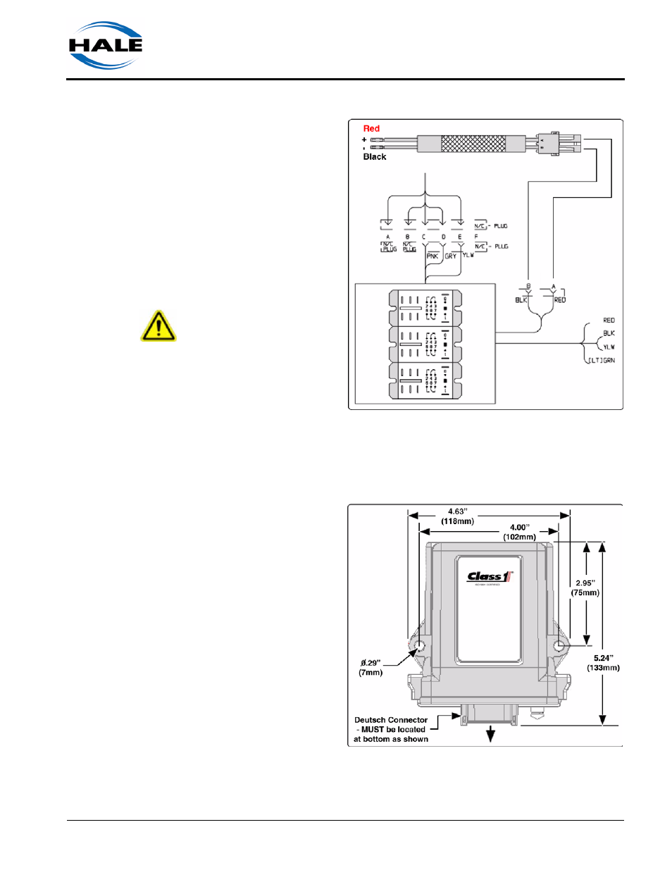
To reduce RF / EM
interference, the relay
assembly power har-
ness must be con-
nected to a “clean”
power source with NO
other electrical equip-
ment attached. (See
Figure 3-4: “Relay
Assembly Power Con-
nection,” on page 17.)
IMPORTANT !
DO NOT CONNECT
POWER SUPPLY HAR-
NESS TO A “LOAD
SHEDDING SYSTEM.”
3.4
DRIVER MODULE
The driver module is
water tight and can be
mounted any place
away form large RF
noise generators.
However, it is impera-
tive to mount the unit
with the connector at
the bottom. (See Fig-
ure 3-5: “Driver Mod-
ule Layout.”)
Refer to separate
manual “Intelli-Tank
High Current 4-Light
Remote Driver Mod-
ule,” p/n: 106759 (12-
15-03), located at the
back of this manual
and packaged with
the unit. Before installation and operation, review this manual in its entirety.
Figure 3-4: Relay Assembly Power Connection
Figure 3-5: Driver Module Layout