3 installation, 1 svs valve actuator, 2 pressure switch mounting – Hale AutoFill-E Tank Refill Control System User Manual
Page 13: Figure 3-1: pressure switch mounting, 3 control panels, Installation, Svs valve actuator, Pressure switch mounting, Control panels, 3installation
13
AUTOFIll-E Installer / User Guide
p/n: 029-0020-81-0
Installer Installation and Calibration
❑
3
Installation
Refer to drawings Plate #: 1024A and Plate #: 1048A for additional installation, wir-
ing and layout information. Both drawings are located at the back of this manual.
3.1
SVS VALVE ACTUATOR
Detailed SVS Valve Actuator System installation instructions are found in a
separate manual (Hale p/n: 029-0020-
90-0). This manual is packaged with
the Valve Actuator and is also available on the Hale web site:
www.haleproducts.com/literature/manuals. Before installing this valve,
review this manual in its entirety.
3.2
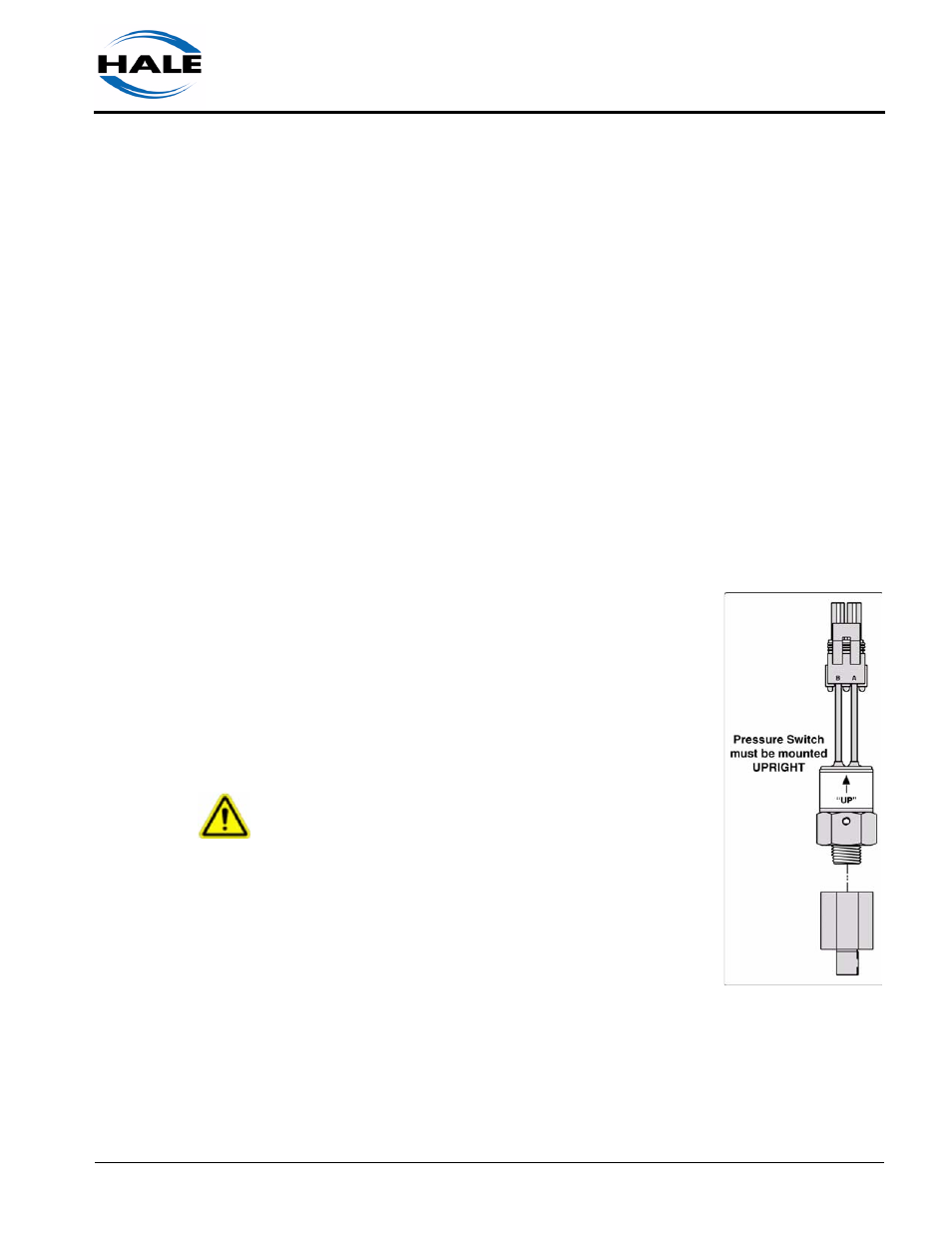
PRESSURE SWITCH MOUNTING
(See Figure 3-1: “Pressure Switch Mounting.”)
The pressure switch (Hale p/n: 200-2560-00-0) pro-
vided with the AutoFill system is mounted to one of
the plugged ports of the suction or INLET side of the
SVS Actuator Valve. A 1/4” FNPT (6.4mm) x 1/8”
NPT (3.2mm) adapter (Hale p/n: 082-0272-02-0) is
provided to assist with installation.
IMPORTANT !
THE PRESSURE SWITCH MUST BE MOUNTED “UP”
(VERTICALLY) FOR PROPER OPERATION. SELECT A
PORT ON THE SVS VALVE THAT ENSURES THE
PRESSURE SWITCH IS MOUNTED CORRECTLY.
3.3
CONTROL PANELS
Refer to Plate #: 1048AA for the suggested panel
installation and cutout dimensions for the three con-
trollers. Plate # 1048AA is located at the back of this manual. Also see Fig-
ure 3-2: “Control Panel Cutouts - Manual, AutoFill and Water Level Gauge”
on page 14.
Figure 3-1: Pressure
Switch Mounting