Search
Directory
Brands
Hale manuals
Equipment
AutoFill-E Tank Refill Control System
Manual
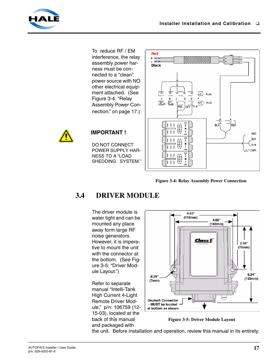
Figure 3-4: relay assembly power connection, 4 driver module, Figure 3-5: driver module layout – Hale AutoFill-E Tank Refill Control System User Manual
Page 17: Installation - continued, Driver module
Text mode
Original mode
Figure 3-4: relay assembly power connection, 4 driver module, Figure 3-5: driver module layout | Installation - continued, Driver module | Hale AutoFill-E Tank Refill Control System User Manual | Page 17 / 55
Pages:
1
…
15
16
17
18
19
…
55
wrong Brand
wrong Model
non readable
See also other documents in the category Hale Equipment:
CAFSPro
(72 pages)
3.3 FoamLogix
(122 pages)
Fyr Pak(2006 to Present)
(39 pages)
Fyr Port
(37 pages)
Master Intake Valve
(46 pages)
MiniCAFS 2.1A (MC50 with FoamLogix System)
(22 pages)
SPV
(16 pages)
Torrent SVS Stainless Steel Valves
(100 pages)
TPM Sistem
(8 pages)
MGA
(16 pages)
Skid
(74 pages)
FoamLogix 3.3
(194 pages)
CAFS Attack
(100 pages)
SMR-AC-140 CAFS
(14 pages)
ESP Priming System
(70 pages)
FoamLogix 2 1A PPK
(2 pages)
FoamLogix Water and Foam Calibrate
(2 pages)
FoamLogix 2.1A-LF Low Foam Flow Calibration
(2 pages)
FoamLogix Water Flow Calibration
(2 pages)