Power Soak 34774 PS-225 Service Manual User Manual
Page 37
31
8.1c Assembly
– Refer to the illustration in Section 10.1for the following description:
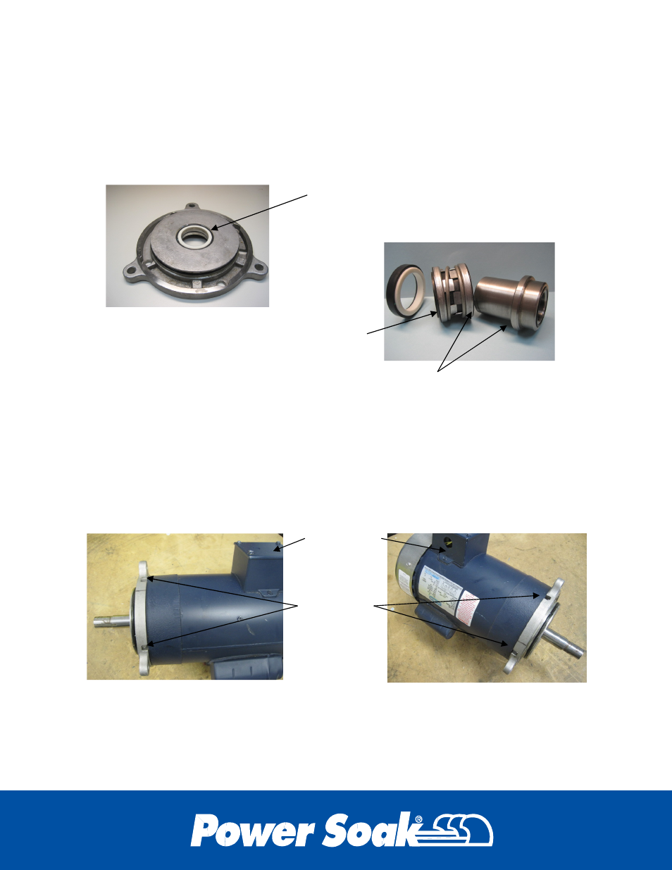
Apply a thin coating of light weight oil such as WD-40 to the outer surface of the
Mechanical Seal base (10) and push the base into the Adapter Plate (13) with the white
surface of the base oriented to the pump side. Apply a thin coating of light weight oil to
the interior of the Mechanical Seal (10) and slide the seal onto the Shaft Sleeve (9) with
the protruding ceramic face of the seal oriented away from the shoulder on the sleeve.
Place the adapter plate on the face of the motor with a drain slot aligned with the
connection box and the other drain slot oriented as shown for the configuration of the
machine. This will allow the connection box to be on the bottom side of the motor when
the pump and motor are assembled onto the volute pump housing. Install the bolts with
a 5/16 Allen wrench.
Flange orientation on units that are
made for Right to Left work flow.
(Sanitize tank on left side of wash tank)
Flange orientation on units that are made
for Left to Right work flow.
(Sanitize tank on right side of wash tank)
Drain slot
alignment
Connection
box
The mechanical seal base is installed into the
adapter plate with the ceramic (white) face
oriented toward the pump side of the plate
The protruding ceramic face of the mechanical
seal is to be oriented to contact the white face
of the mechanical seal base.
The shaft sleeve will slide through the mechanical seal oriented
so that these two faces make contact with each other