9 push button membrane – Power Soak 34774 PS-225 Service Manual User Manual
Page 27
21
6.9 Push Button Membrane
The buttons and lights on the front of the control panel are made into a plastic
membrane that is sandwiched between the plastic overlay and the sheet metal face of
the enclosure cover. A “ribbon cable” with a connector on the end of the cable attaches
to the buttons and lights. The ribbon cable fits through a slot in the sheet metal door on
the control panel and pugs into the UPM to allow the buttons to signal the UPM for the
start, stop and unload functions. It also allows the UPM to illuminate the lights on the
membrane. The membrane and overlay are bonded to the sheet metal with an
adhesive. If the membrane malfunctions, the overlay and the membrane will both have
to be replaced. The adhesive is strong enough that the membrane and overlay cannot
be removed without damage to both components. The following illustrations show how
to check the operation of the push buttons.
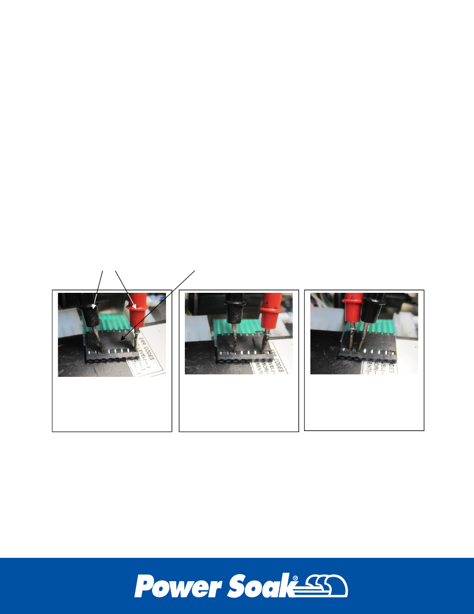
Disconnect the ribbon connector and apply the leads of an ohm meter as shown. If the
ohm meter does not show continuity when the button is pressed and a break in
continuity when the button is released then the membrane must be replaced.
START BUTTON
First and sixth from the
right side of the connector
STOP BUTTON
Second and sixth from
the right side of the
connector
UNLOAD BUTTON
Seventh and sixth from
the right side of the
connector
Ohm meter probes
Ribbon connector disconnected from the UPM