1 programming interface – Power Soak 34774 PS-225 Service Manual User Manual
Page 21
15
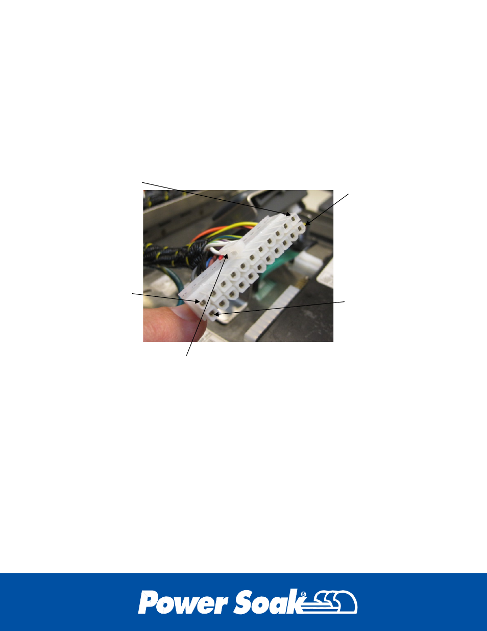
Identification of the UPM connector terminals is helpful for troubleshooting.
Disconnecting the wiring harness connector and conducting voltage or ohm
measurements on the terminals in the connector will help determine the condition of the
components connected to the wiring harness. The pin numbers are identified on the
schematic for determining the component connections.
The 22 pin connector for the UPM is identified on the schematic as “J1”. It carries the
majority of the communication signals to and from the UPM. The connector is designed
so that it can only be connected in the correct orientation. Identification of the pin
numbering is shown below.
6.1 Programming Interface
The programming interface allows direct access to the settings in the UPM operating
program. The functions in the program can be turned “on” or “off” to tailor the machines
operation to a specific application. The timers can be adjusted to coordinate with
functions such as the fill rate of the wash and sanitizer tanks. Explanation for how to set
these control functions and timers is located in the programming manual.
The programming interface is installed in the mounting bracket by separating the outer
case from the inner frame. Press the thumb tabs toward the center of the case, and
then pull the outer case away from the front face.
Pin 12 is located
in the upper left
corner when
facing the
connector
Pin 1 is located in
the lower row on
the left corner
when facing the
connector
Pin 11 is located
in the lower right
corner when
facing the
connector.
The lower row is
numbered 1 thru
11
Pin 22 is located
in the upper right
corner when
facing the
connector.
The upper row is
numbered 12 thru
22
Orient the connector with the clip on top as shown