5 power transformer – Power Soak 34774 PS-225 Service Manual User Manual
Page 24
18
The wiring harness connectors for the Triac gates must be connected to the proper
location. The connector location is matched to the gate connection by the location in
the wiring harness. The first wire connector exiting the wiring harness will attach to the
first gate connection on the heater control Triac. On a single phase machine or when a
heating element is not used, the additional Triacs will not be installed and the
connectors will be tied to the wiring harness. The connectors have a common
connection that is in series with each of the connectors. When a connector is
disconnected from a Triac, the connectors to the right of that connector will not operate.
The Triac relays are bolted to the heat sink which is mounted on the back of the control
enclosure. When replacing a Triac relay, be sure that the mounting surface is clean and
the back surface of the relay makes good contact with the heat sink in order to get the
proper cooling of the relay.
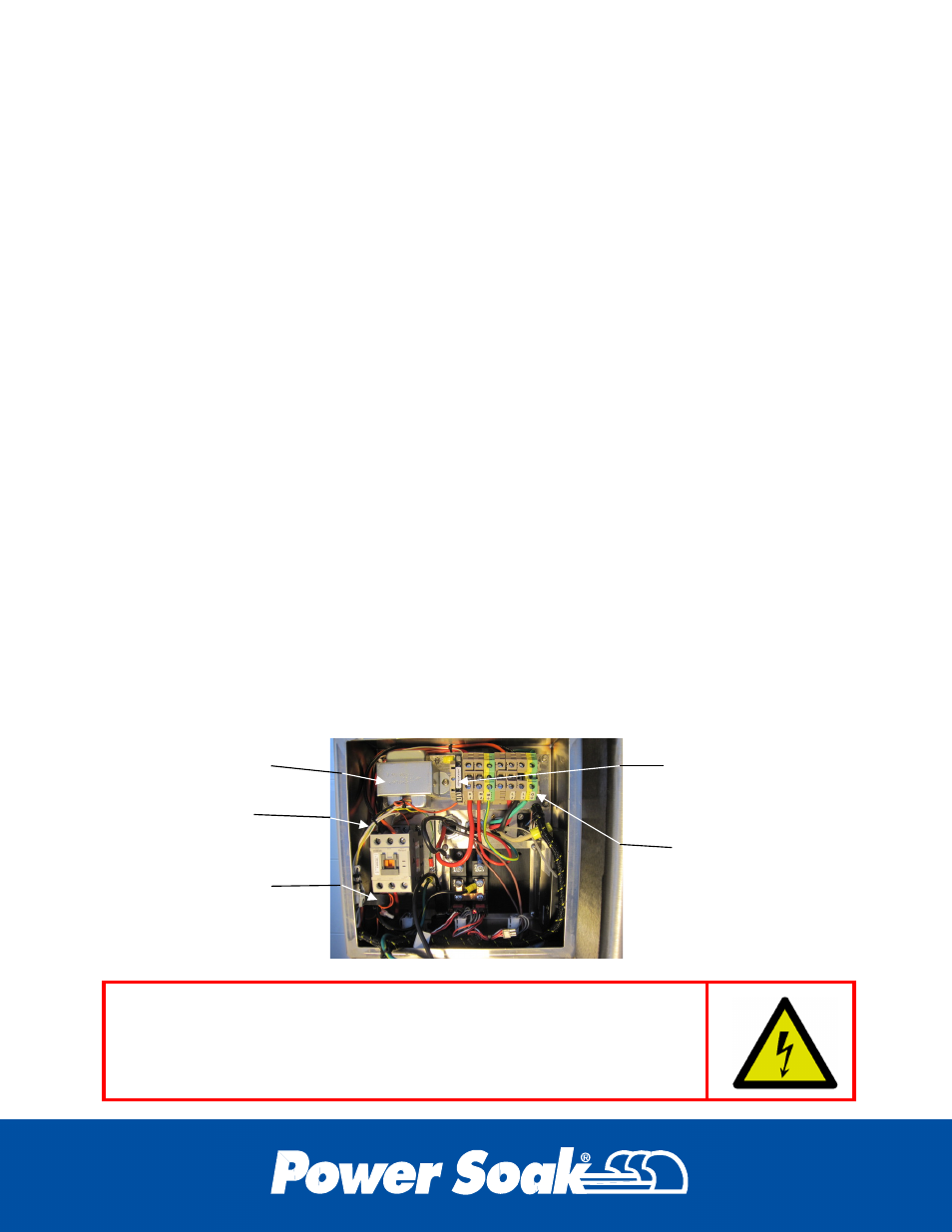
6.5 Power Transformer
The power transformer, located in the upper left corner of the control enclosure, is used
to convert the incoming high voltage to 24VAC with a 12VAC center-tap. The 12VAC is
used for the thermal protection circuit while the 24VAC is used for control functions and
the chemical dispenser. The transformer has multiple input voltage connections and
must be connected for the correct voltage that is supplied to the machine. Three of the
wire connections are made using a “crimp” connector. When replacing a transformer,
new crimp connectors or wire nuts will be required. To test the transformer, verify that
the input voltage is correct. This can be done between the L1 and L2 terminal
connections. Verify the output voltage of the transformer by reading 24 volts across the
yellow and orange output wires, and 12 volts between the center-tap (grey connected to
black & white wires) and each of the other outputs. These voltages can be verified at
the three wire nuts on the internal wiring harness near the Transformer. If a low voltage
reading occurs, disconnect the output wires and check again. If the voltage returns to
24VAC then check other components for a connection to ground (short circuit).
The transformer is connected to high voltage electricity. The power to
the machine must be turned off at the circuit breaker in the wall
mounted enclosure when working on the transformer. Failure to turn
off the power will result in serious injury and possibly death.
Transformer
Contactor
Load Sensor
Terminal Blocks
Fuse Block