Lokar Ford C4 and C6 Hi-Tech Kickdown Kit User Manual
Lokar For the car
NOTE: This Lokar Kickdown Kit is designed to be installed with a Lokar Carburetor
Bracket and Springs, part # SRK-4000 (available separately, not included). The
Lokar Kickdown Cable is designed to be cut-to-fit.
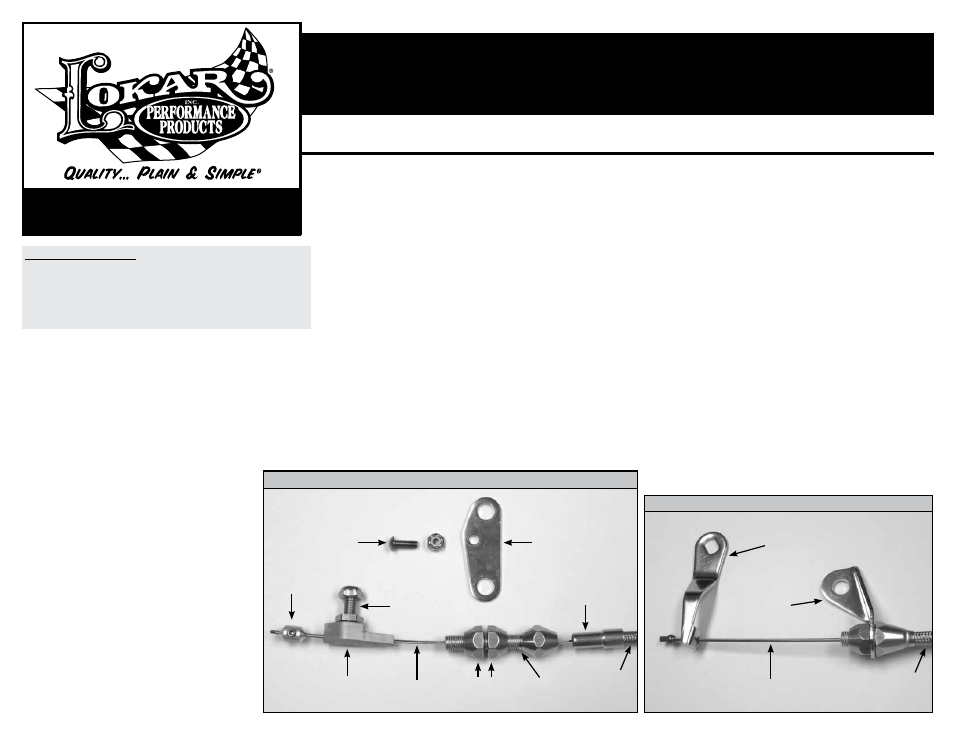
Refer to Figs. 1, 2 and 3 for the component names.
Step 1: Remove the cable end stop, kickdown throttle body fitting, and kickdown cable
adjuster from the new Lokar kickdown cable. Leave the kickdown mounting
bracket on the kickdown cable adjuster.
DO NOT remove the ferrule from the
cable housing if the cable housing is braided stainless steel. Remove the inner
wire from the cable housing, and remove the kickdown lever from the inner wire.
Step 2: Install the kickdown lever onto the transmission, with the cable hole towards the
transmission as shown in
Fig. 4 for C4 and Fig. 5 for C6.
Step 3: Install the trans cable bracket and the cable housing onto
the transmission as shown in
Fig. 4 for C4 and Fig. 5 for C6.
NOTE: These photos show the inner wire, which SHOULD NOT
be installed at this point. C4 uses an existing transmission
bolt. The C6 kit includes a 5/16"-18 x 1" button head bolt
and locknut for the trans cable bracket.
NOTE: On the C6
transmission, the cable mounting bracket goes
underneath
the casting lug on the side of the transmission.
Step 4: If the throttle cable has already been installed, disconnect
the throttle cable from the carburetor. If the engine
already has a Lokar carburetor bracket installed, remove
the throttle cable adjuster. Leave the carburetor bracket
in place. If the engine does not have a Lokar Carburetor
Bracket already installed, install one now, following the
installation instructions that were provided with the Lokar
Carburetor Bracket.
Step 5: The kickdown mounting bracket mounts onto the back side
of the Lokar carburetor bracket (not included). The throttle
cable adjuster will pass through the top hole in both the
new kickdown mounting bracket AND the carburetor
bracket. Position the kickdown mounting bracket behind
the carburetor bracket so that the 5/16" diameter holes
at the top of both brackets are aligned, the small 3/16"
diameter holes near the center of the two brackets are
aligned, and the kickdown cable adjuster is offset towards
the left side of the vehicle.
Building American Quality… With A Lifetime Warranty!
General Installation Notes:
Please read these instructions completely before beginning the installa-
tion. If you have any questions please call.
Before beginning the installation, disconnect the negative battery cable
and use wheel chocks to block the vehicle's wheels.
We recommend using anti-seize lubricant on all aluminum threads.
TOLL FREE 1-877-469-7440 • [email protected] • www.lokar.com
®
Ford C4 and C6 Hi-Tech Kickdown Kit Installation Instructions
INS0007 Rev. 08/05/2014
Page 1
© 2005 Lokar, Inc.
Ford C4 and C6 Hi-Tech Kickdown Kit
Installation Instructions
Step 5: (Continued) Attach the kickdown mounting bracket to the carburetor bracket
using the supplied #8-32 x 1/2" button head bolt and nylock nut through
the small 3/16" diameter center holes in both brackets, but do not tighten
yet. Insert the throttle cable adjuster (with the rear nut still installed) from
the rear through the top holes in both brackets. Position it so that the
threaded part of the throttle cable adjuster is approximately centered in the
carburetor bracket. Install the front adjuster nut.
Tighten the throttle cable adjuster nuts, the button head bolt and nut, and
the kickdown cable adjuster nuts.
Fig. 6
Step 6: Route the cable housing up to the kickdown cable adjuster. Make sure
that the inner wire is removed from the cable housing. If the cable housing
is braided stainless steel, slide the ferrule down the housing towards the
transmission, away from the end that is being cut.
DO NOT remove the
ferrule from the braided stainless steel housing! If the cable housing is
black universal, remove the ferrule.
Measure the distance between the kickdown cable adjuster and the trans
cable bracket. Add 1" to the measurement and cut the cable housing to
that length.
If the kickdown cable has the braided stainless steel housing, wrap tape
around the area to be cut and use a cutoff wheel or fine-toothed hacksaw.
If the kickdown cable has a black universal housing, cut the cable housing
with heavy duty 8” diagonal cutting pliers or a hacksaw. Lokar recommends
Klein brand Diagonal Cutting Pliers, # D2000-28 available at The Home
Depot or through W. W. Graingers, Part # 4A838.
After cutting the cable housing, put the ferrule back in place at the end of
the cable housing. Insert the cable housing and ferrule into the kickdown
cable adjuster.
Step 7: The tear drop will be attached to the carburetor throttle arm by the hex carb
fitting. Separate the hex carb fitting from the kickdown throttle body fitting.
Install the hex carb fitting and the tear drop onto the carburetor throttle arm
as shown in
Fig. 7. Hook the springs to the tear drop and tighten the nylock
nut on the hex carb fitting. Then back the nylock nut off just enough so that
the tear drop can pivot freely.
Step 8: Pass the inner wire through the hole in the kickdown lever on the
transmission, and then thread it up through the cable housing to the
carburetor.
Step 9: Before connecting the kickdown cable to the carburetor, make sure that the
throttle linkage is properly adjusted. Verify at the carburetor that the throttle
is wide open while you have a helper hold the accelerator pedal to the
floor. Once you are sure that the throttle linkage is adjusted correctly, slide
the kickdown throttle body fitting onto the kickdown cable inner wire, and
connect the kickdown throttle body fitting to the hex carb fitting.
Step 10: This step will also be much easier with a helper. Slide the kickdown cable
end stop onto the inner wire. Move the throttle to wide open and hold it
there while pulling the kickdown inner wire as tight as possible. Slide the
cable end stop up against the kickdown throttle body fitting and tighten the
set screw using the supplied 5/64" Allen wrench. Release the throttle.
When the kickdown cable is properly adjusted you should be able to
open the throttle to the wide open position without interference from the
kickdown cable; and with the throttle wide open, you should not have any
slack in the kickdown cable. The kickdown cable also should not prevent
the throttle from returning to the fully closed position.
Double check to be sure that all carburetor, throttle and kickdown linkages
operate freely without binding, then te
DO NOT remove the ferrule from the
cable housing if the cable housing is braided stainless steel. st drive. Once
the kickdown cable is correctly adjusted and operating properly you can cut
off the excess inner wire, leaving about 1/2" extending beyond the cable end
stop to allow for future adjustment if needed.
Final installation should look like
Fig. 4 or 5 and Fig. 7.
#8-32 x 1/2" Button Head
Bolt with Nylock Nut
Kickdown
Mounting
Bracket
Cable End
Stop
Kickdown Throttle
Body Fitting
Inner
Wire
Inner
Wire
Trans Cable
Bracket
Kickdown
Lever
Adjuster
Nuts
Kickdown
Cable Adjuster
Cable
Housing
Cable
Housing
Hex Carb
Fitting with
Nylock Nut
Ferrule
Fig. 1
Fig. 2
Carburetor End
Transmission End, C4