Lokar Throttle Plate with Kickdown & Spring Return Kit for 4150 Style Carburetor User Manual
Lokar For the car
Building American Quality… With A Lifetime Warranty!
General Installation Notes:
Please read instructions completely before beginning installation. If you
have any questions please call.
Before starting installation, scotch vehicle tires to avoid accidental move-
ment of the vehicle. Disconnect negative battery cable before beginning
installation.
This kit is designed to be used with a Lokar Throttle Cable and/or Kickdown Cable.
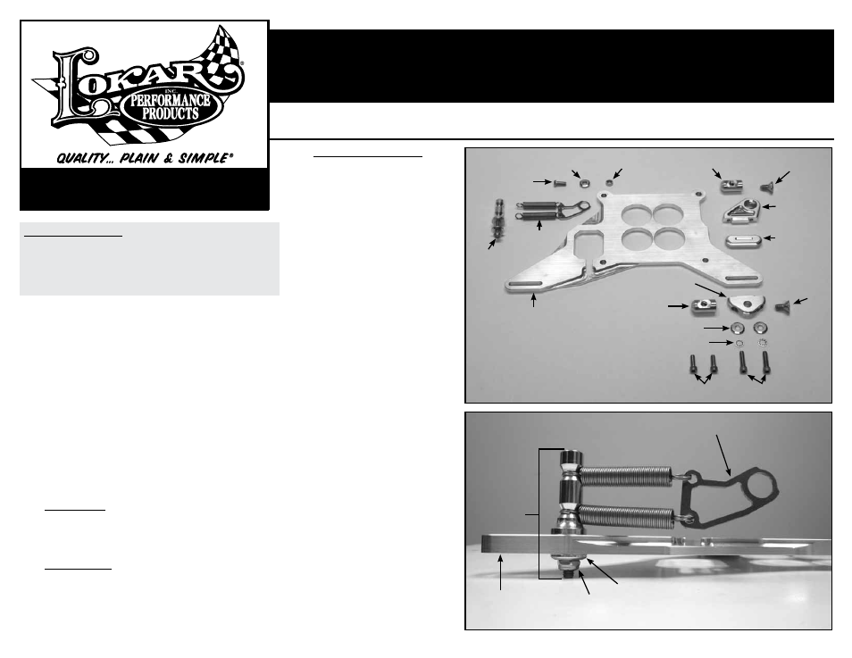
Refer to Fig. 1 for the component names.
Step 1: Remove the 1/4"-20 thin nylock nut and the post washer from the
spring stand assembly. Install the spring stand with the springs and
throttle tab onto the top side of the throttle cable mounting bracket,
into the slot at the front left corner. Install the post washer (beveled
edge out) and 1/4"-20 thin nylock nut on the bottom.
Fig. 2
Step 2: If you are going to be mounting a throttle cable onto the mounting
bracket, assemble the throttle cable stand and cable stud, using the
3/8"-16 x 3/4" flat head bolt.
Fig. 3 The flat on the cable stud goes
towards the rear. Make sure the cable stud is angled correctly so that
the throttle cable inner wire will be aligned with its connection point
on the carburetor.
If you are going to be mounting a kickdown cable onto the mounting
bracket, assemble the kickdown cable stand and cable stud, using
the 3/8"-16 x 3/4" flat head bolt.
Fig. 3 The flat on the cable stud
goes towards the rear. Make sure the cable stud is angled correctly so
that the kickdown cable inner wire will be aligned with its connection
point on the carburetor.
Step 3: Throttle Cable Only: On the top side of the mounting bracket, insert the
throttle cable stand into the slot at the rear left corner, with the cable
stud pointing outwards. Install the 1/4"-20 x 3/4" socket head bolts
from the bottom up through the throttle cable mounting bracket, with
an internal-tooth lock washer and a post washer (beveled edge out) on
each one.
Fig. 4
Step 3: Kickdown Cable Only: On the bottom of the throttle cable bracket,
insert the kickdown cable stand into the slot in the rear left corner,
with the cable stud pointing outwards. Insert the threaded cap into
the slot from the top. Install the 1/4"-20 x 1" socket head bolts from
the bottom up through the kickdown cable stand and into the thread-
ed cap.
Fig. 5 Make sure you are using the 1" long (thread length, not
total overall length) bolts!
Step 3: Throttle Cable and Kickdown Cable: On the
bottom of the throttle cable bracket, insert
the kickdown cable stand into the slot in
the rear left corner, with the cable stud
pointing outwards. Insert the throttle cable
stand into the slot from the top, directly
above the kickdown cable stand, with the
cable stud pointing outwards. Install the
1/4"-20 x 1" socket head bolts from the
bottom up through the kickdown cable
stand and into the throttle cable stand.
Fig. 6 Make sure you are using the 1" long
(thread length, not total overall length) bolts!
Step 4: Place a new carburetor gasket (not
included) onto the intake manifold. Then
install the mounting bracket onto the intake
manifold with the cable stand(s) and spring
assembly on the left. Place a new carburetor
gasket (not included) on top of the mount-
ing bracket, and install the carburetor.
Step 5: Place the tab bushing onto the 1/4"-28 x 5/8"
button head bolt with the larger diameter
side facing the head of the bolt. Insert
the button head bolt with the tab bushing
into the large round hole in the spring tab.
Install this assembly into the return spring
hole on the carburetor throttle arm, and
secure with the 1/4"-28 nylock nut. Make
sure the recess in the tab bushing is seated
over the lip on the carburetor throttle arm,
and that the spring tab will swing freely on
the throttle arm.
Fig. 7
Step 6: Install the throttle and/or kickdown cables
following the instructions that came with
those kits. Adjust the angle of the cable
studs if needed.
Once the throttle and/or kickdown cables
have been installed and adjusted, mark the
position of the cable studs. Remove the
3/8"-16 x 3/4" bolts from each of the cable
studs. Apply blue thread locking compound
to each bolt, and reassemble. See
Fig. 8 for
a completed installation.
NOTE: Before starting engine, check the
carburetor and throttle linkage to make sure
there is no binding and that the throttle
returns all the way to the closed position.
TOLL FREE 1-877-469-7440 • (865) 966-2269 • FAX (865) 671-1999 • [email protected] • www.lokar.com
®
Throttle Plate with Kickdown & Spring Return Kit
for 4150 Style Carburetor Installation Instructions
Throttle Plate with Kickdown & Spring Return Kit
for 4150 Style Carburetor Installation Instructions
INS0133 Rev. 04/11/13
Page 1
© 2013 Lokar, Inc.
Fig. 1
Fig. 2
1/4"-28 x 5/8"
Button Head Bolt
Tab
Bushing
Nylock
Nut
Cable
Stud
3/8"-16 x 3/4"
Flat Head Bolt
3/8"-16 x 3/4"
Flat Head Bolt
1/4"-20 x 1"
Socket Head Bolts
1/4"-20 x 3/4"
Socket Head Bolts
Spring Tab
Spring Stand
Assembly
Mounting
Bracket
1/4"-20 Thin
Nylock Nut
Post Washer
Internal Tooth Lock Washers
Post Washers
Cable Stud
Kickdown
Cable Stand
Mounting
Bracket
Spring
Stand
Assembly
Springs and
Spring Tab
Throttle Cable
Stand
Threaded Cap