HT instruments HT7051 User Manual
Page 16
HT2055
EN - 15
7 HOW TO PERFORM THE MEASUREMENTS
7.1 THEORY
OF
STEP/CONTACT VOLTAGE MEASUREMENTS
An earth electrode / grid depleted into ground has a certain resistance, depending on its
size, surface (oxides on the metal surface) and the soil resistivity around the electrode.
The earth resistance is not concentrated in one point but is distributed around the
electrode. Correct connection of exposed conductive parts assures that the voltage on
them stays below dangerous level in case of a fault.
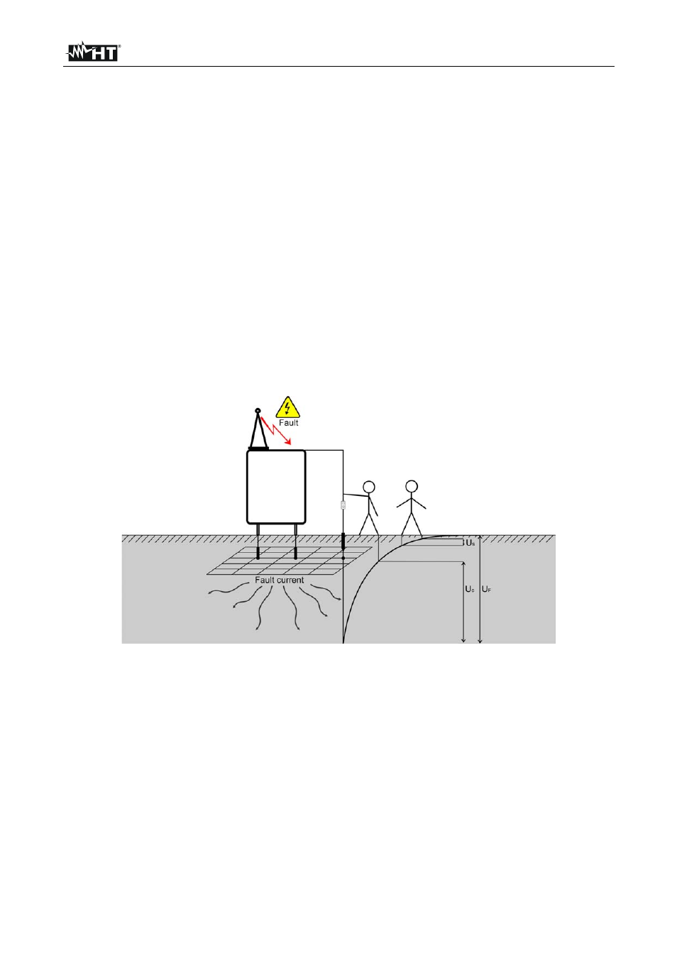
If a fault happens a fault current will flow through the earth electrode. A typical voltage
distribution occurs around the electrode (the “voltage funnel”). The largest part of the
voltage drop is concentrated around the earth electrode. The Fig. 16 shows how fault, step
and contact voltages occur as a result of fault currents flowing through the earth electrode
/ grid in the ground.
Fault currents close to power distribution objects (substations, distribution towers, plants)
can be very high, up to 200 kA. This can result in dangerous step and contact voltages. If
there are underground metal connections (intended or unknown) the voltage funnel can
get atypical forms and high voltages can occur far from the point of failure. Therefore the
voltage distribution in case of a fault around these objects must be carefully analyzed.
Fig. 16: Dangerous voltages on a faulty earth system
The guidelines define limit values of step/contact voltages depending on the time of fault
elimination by the protection devices (typically declared by the Mains Energy provider). If
the value of fault voltage is over this limit it is necessary to verify that the values of
step/contact voltages in some potentially dangerous points of the plants (e.g: access
areas, close to metal structures normally de-energized, gates, safety nets, etc) fall within
standard values.