FEC AFC1500 User Manual
Page 92
Chapter 6: Fastening Instructions
Page 6-6
6.1.2 Angle Control Method.
In Angle Control method, fastening is performed based upon attaining a desired torque value
and then rotating the fastener a specified number of degrees,
while monitoring the Torque of the
fastener and time. Additional monitor items (limits) can be set to enhance the systems ability to deter-
mine if the fastener was properly secured (Section 6.2).
Fastening can be performed from 1 to 3
incremental steps that will successively secure the fastener to a specified torque or angle
value before attaining the final number of degrees of rotation.
Angle Control method is primarily used when greater control of clamp load is required. (Angle
Control specs. are developed through testing of the joint and fastener characteristics and
therefore should not be attempted unless testing is performed)
NOTE: All setting recommendations are based upon common fastening applications.
Applications that experience high Prevailing torque, excessive joint compression or
other unique characteristics must be set with these characteristics in mind.
NOTE: When performing multiple step Angle control fastening, the rotation Angle
should be performed as one continuous operation. There should be no intermediate
stop/synchronization points once Snug Torque has been sensed and rotation angle is
being controlled. Under special conditions multiple steps can be performed using in-
termediate Torque or Angle stop/synchronization points.
{
{
{
{
One-Step Fastening
P
One-Step fastening will be used primarily for joints that have no requirement to synchronize with
another spindle during the final stage of the rundown.
1. Angle control commences at SNUG TORQUE. All angle values are referenced from this point.
2. Once SPEED CHANGE TORQUE is reached or FREERUN REVOLUTIONS expires, the system will
switch from FREERUN SPEED to SLOWDOWN SPEED and continue to fasten to 1ST
TORQUE/ANGLE.
3. The system will fasten to the 1ST TORQUE/ANGLE value during the specified 1ST TIME. 1ST
TORQUE/ANGLE must be reached within the 1ST TIME limits or a reject will occur.
4. Upon reaching 1ST TORQUE/ANGLE, 1ST TIME ends and FINAL TIME begins. 1ST
TORQUE/ANGLE is the shift point to TORQUE SPEED.
5. The system will fasten to STANDARD ANGLE using TORQUE SPEED during FINAL TIME.
STANDARD ANGLE must be reached within the FINAL TIME limits or a reject will occur.
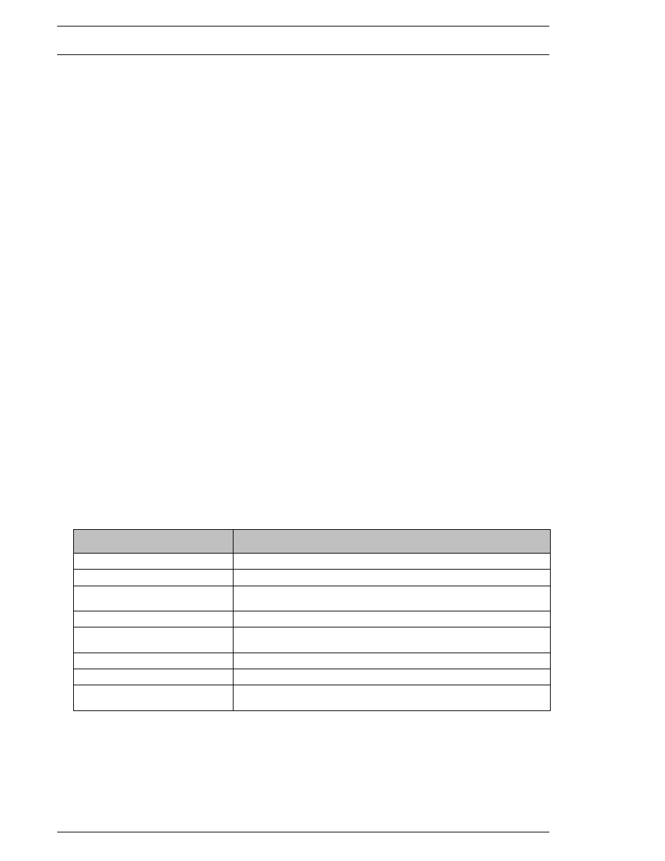
FUNCTION
RECOMMENDATION / COMMENT
SPEED CHANGE TORQUE
30% of SNUG TORQUE
THRESHOLD TORQUE
Start point of 1
st
torque rate monitoring (section 6.2)
1ST TORQUE/ANGLE
80% of SNUG TORQUE
Used for RATE/TIME settings and TORQUE SPEED initiation.
SNUG TORQUE
Angle Control Start Point
CROSSOVER
TORQUE/ANGLE
Start point of 3
RD
torque rate monitoring (section 6.2)
STANDARD ANGLE
Engineered product fastening specification
1ST TIME HIGH/LOW LIMIT
Acceptance range to reach 1ST TORQUE/ANGLE setting
FINAL TIME HIGH/LOW LIMIT
Acceptance range to go from 1ST TORQUE/ANGLE to
STANDARD ANGLE