3 unit arrangement, Page 4-4, Resolver – FEC AFC1500 User Manual
Page 48: Motor resolver, Motor, Chapter 4: system setup and wiring, See preceding page for actual unit width
Chapter 4: System Setup and Wiring
Page 4-4
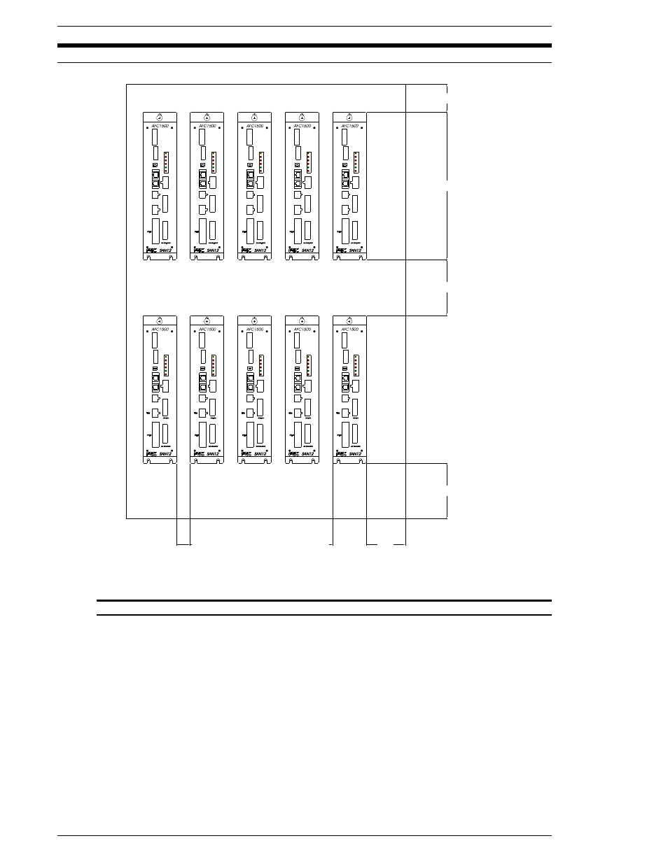
4.3
Unit Arrangement
** See preceding page for actual unit width
FIG. 4-3 Unit Arrangement
The Units may be mounted in any desired configuration as long as the minimum spacing re-
quirements are not neglected.
When installing duct above and below the Units, ensure that adequate space is provided to
allow for removal and installation of the Units without removal of the mounting screws.
The components of the AFC1500 System are designed with slotted mounting holes for easy
mounting to the back panel of the enclosure using standard 8-32 screws.
TYP 13
70
100
60**
100
50
265
SW1
RS
MON.
RUN
485
BYPASS
SW1
BYPASS
RS
485
RUN
MON.
T/D
CON1
POWER
BUSY
RESOLVER
CON1
BUSY
POWER
SV.
REJ.
ACC.
ABN.
MON.
RS
485
BYPASS
RUN
SW1
MOTOR
RESOLVER
ABN.
ACC.
REJ.
SV.
485
MON.
RS
RESOLVER
SW1
BYPASS
RUN
ABN.
REJ.
ACC.
SV.
POWER
BUSY
CON1
MOTOR
MOTOR
CON1
BUSY
POWER
SV.
ABN.
REJ.
ACC.
RESOLVER
CON1
POWER
BUSY
T/D
MON.
BYPASS
RS
485
RUN
SW1
SV.
RESOLVER
REJ.
ACC.
ABN.
SV.
MON.
T/D
RUN
485
BYPASS
RS
RESOLVER
REJ.
ACC.
ABN.
SW1
BUSY
POWER
CON1
BYPASS
485
MON.
RS
RUN
SW1
RESOLVER
POWER
BUSY
ABN.
SV.
ACC.
REJ.
CON1
MOTOR
RESOLVER
MON.
RS
485
BYPASS
RUN
SW1
POWER
BUSY
ABN.
SV.
ACC.
REJ.
CON1
MOTOR
BYPASS
MON.
T/D
RS
RUN
485
SW1
SV.
RESOLVER
REJ.
ACC.
ABN.
CON1
BUSY
POWER
RESOLVER
SV.
BYPASS
T/D
MON.
RS
485
RUN
REJ.
ACC.
ABN.
SW1
CON1
BUSY
POWER