FEC AFC1500 User Manual
Page 59
FEC AFC1500 Operations Manual
Chapter 4: System Setup and Wiring (Rev. 6:10/09)
Page 4-15
4.7
Wiring PLC I/O
All interface devices must accommodate active true low logic for correct operation with
AFC1500 SAN Unit inputs and outputs (I/O).
Optional Field bus interface is available when using a Multi Unit.
Outputs are rated at 12~24 VDC, 200mA.
Open collector sink outputs pull the input device signal low (0 VDC) when activated.
Inputs are normally high and activated when pulled low (0 VDC).
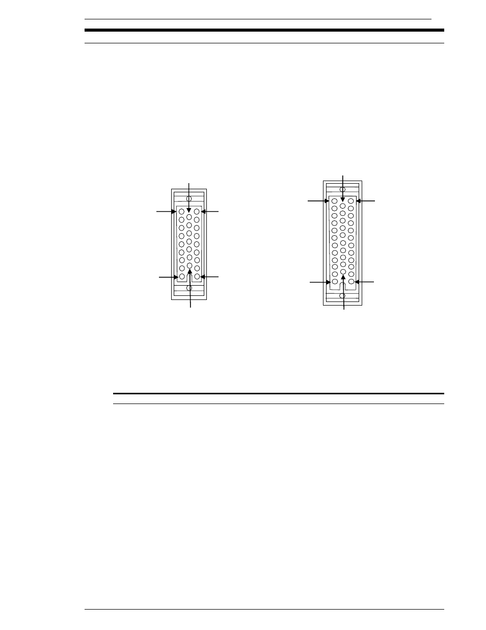
SAN2 (25 pin) I/O connection
SAN3 (34 pin) I/O connection
Mating connector: Honda MR-25M
Mating connector: Honda MR-34M
As viewed from the front of the SAN Unit.
FIG. 4-7-1 San Unit PLC Connector
Note: If you are adapting from an older SAN 25pin cable connector to a new SAN3 34 pin con-
troller, use cable adapter FEB-1522. This will allow the use of your old 25 pin I/O cable for
use with a new SAN3 Controller unit.
CAUTION:
The PLC I/O wiring must be routed a minimum of 300 mm away from
any transient high voltage sources. Cable length must not exceed 50 feet.
DO NOT connect a positive DC voltage source to the output common.
23
34
12
1
22
13
17
25
9
1
16
10