Spark pickup check, Replacement parts – GxT Ferret 63 DIAGNOSTIC ENGINE ANALYZER User Manual
Page 33
SPARK PICKUP CHECK
With this test the analyzer is put in a special test mode
that produces simulated spark pulses to test the Spark
Pickup. At the same time some other internal function
self-tests are done.
SPARK PICKUP SELF TEST
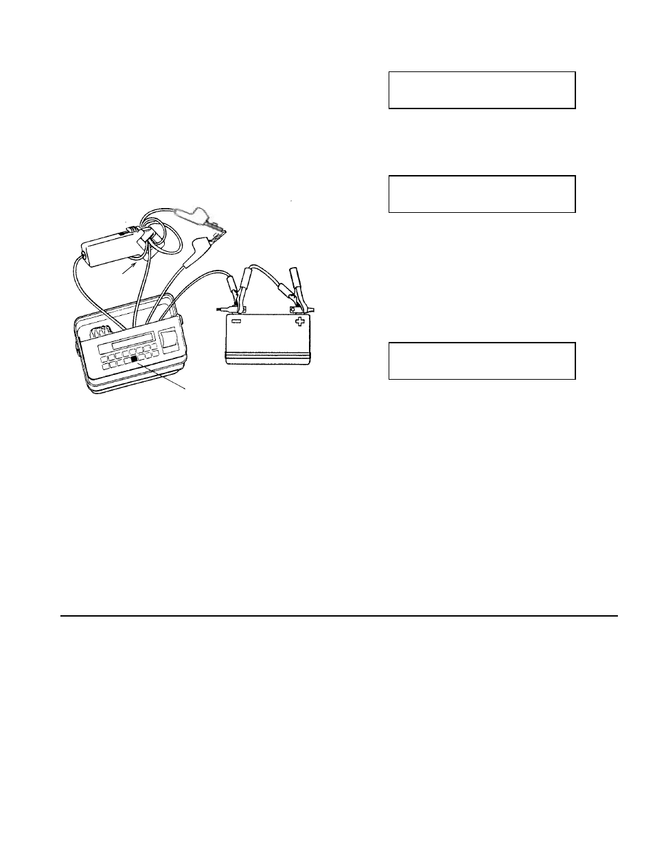
Refer to the connection diagram when doing the follow-
ing steps. There must not be any connections other than
the following:
1. Pass the green Coil Primary Clip wire four times
through the Spark Pickup opening such that the clip end
comes out the spark plug label side. Close the pickup
jaw.
2. Connect the green Coil Primary Clip to the red Aux-
iliary Clip.
3. Connect the analyzer red BatterY Clip to 12 volt bat-
tery plus.
4. Press and hold MESSAGE while connecting the ana-
lyzer black Battery Clip to battery minus.
5. If all connections and operations are correct the dis-
play will show:
Press START.
If a wire is not hooked up properly, or broken it will
show:
Press START to retry the test. If the hookup is okay one
of the clip wires is probably open. Verify by doing the
“COIL PRIMARY LEAD CHECK” and the “AUXILIARY
VOLTMETER CHECK”. If the wires check okay the
analyzer is probably broken.
If the connections are good but the spark pickup is not
working it will show:
Try wiggling the pickup lead terminations and check the
core contacts for a gap or breaks. Double check the di-
rection of the coil Primary Clip wire through the pickup.
If the pickup is working the “no SPARK PICKUP Signal”
line will go away leaving only the “1638 RPM output
OKAY” to show that all is working.
With this arrangement the pulses in the test lead may be
used to check the calibration of other secondary ignition
tachometers. More turns may be needed in other pick-
ups to sense the pulses. (4 stroke scale, 1% accuracy)
6. Leave the self test mode by pressing any test key.
COIL PRI & AUX CONNECTED
4 times thru SPRK PICKUP
BAD Connection
FIX and START to RETEST
1638 RPM output OKAY
no SPARK PICKUP Signal
-31-
1638 RPM
PULSES
4X
THROUGH
GREEN
RED
RED
BLACK
Hold MESSAGE key
during power up.
12 VOLT
REPLACEMENT PARTS
PART NUMBER
Coil Primary/Auxiliary Clip Lead ....................W004-93
Battery Clip Lead ...........................................W004-02
Extension Harness, 8' ...................................W000-04
Inductive Spark Pickup ...................................X008-01
Inductive Amp Probe, 5' .................................X000-02
Timing Light ....................................................X006-01
Printer Paper, Pk. of 3 rolls ............................H013-01
Paper Spindle ................................................ G016-09
Printer Cover ................................................. G016-08