Icom IC-F610 User Manual
Page 31
26
8
CONNECTION AND MAINTENANCE
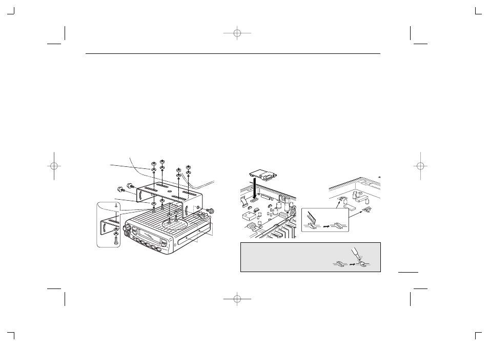
D Mounting the transceiver
The universal mounting bracket supplied with your transceiv-
er allows overhead mounting.
• Mount the transceiver securely with the 4 supplied screws
to a thick surface which can support more than 1.5 kg.
Flat washer
Spring washer
When using
self-tapping screws
■Optional UT-109 /UT-110
installation
q Turn power OFF, then disconnect the DC power cable.
w Unscrew the 4 screws, then remove the bottom cover.
e Cut the print pattern on the PCB at the TX mic circuit (A)
and RX AF circuit (B) as shown in the following figure.
r Install the scrambler unit as shown in the following left.
t Return the bottom cover and screws to the original posi-
tion.
NOTE: Be sure to re-solder the above dis-
connected points, otherwise no TX modu-
lation or AF output is available when you
remove the scrambler units.
A
B
Front panel
• Install the unit
• Cut the print pattern
IC-F610_MPT-2.qxd 05.5.10 1:00 PM Page 31 (1,1)