IntraServer Technology ITI-90-100250 User Manual
Page 36
Page 36 of 83
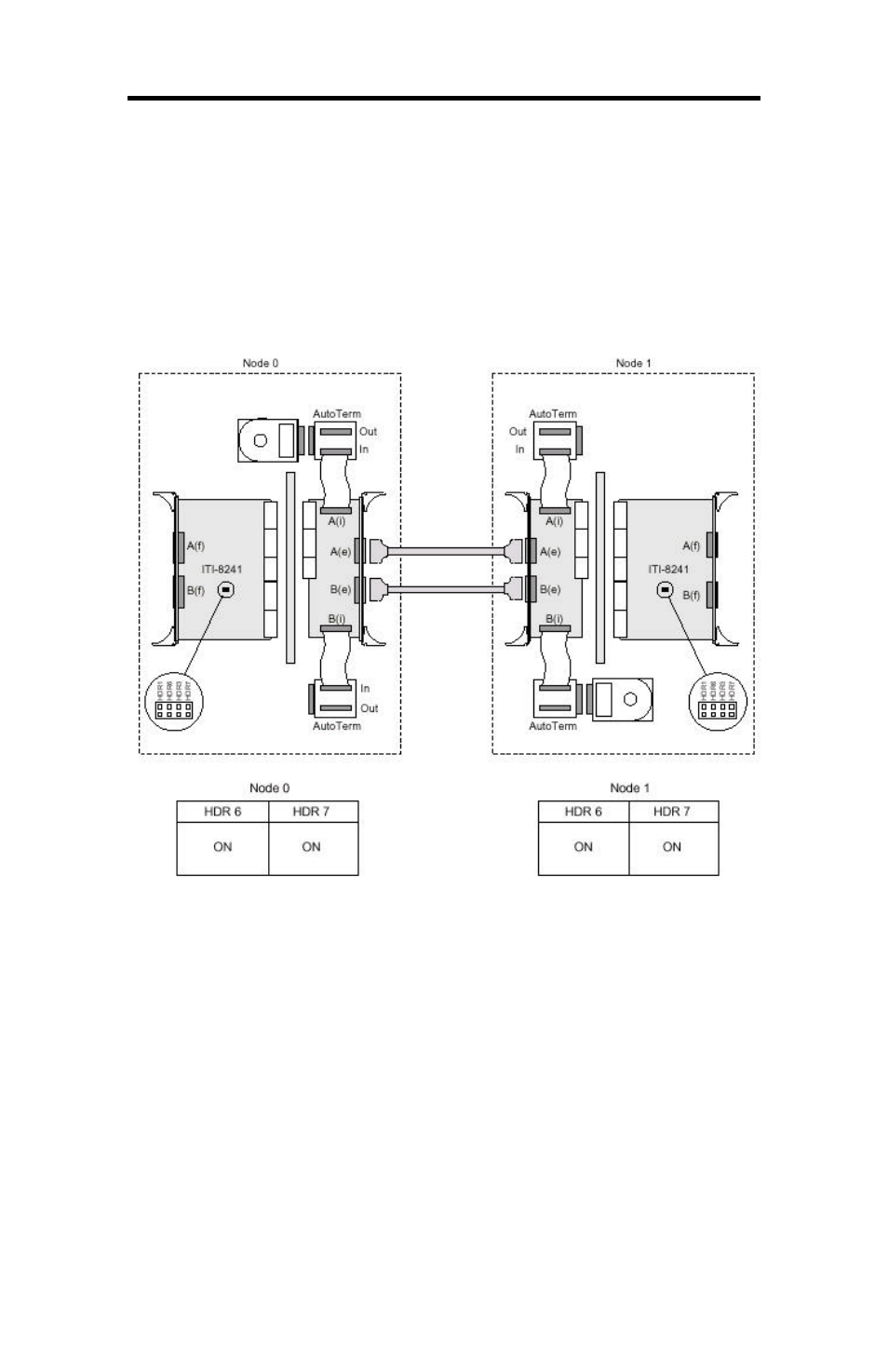
The configuration example figures in this section show how the shared disk
drives, the cables, and the controller cards are physically located in Node 0
and Node 1.
Table 6
shows the recommended termination scheme and SCSI ID
settings for one mirrored drive configuration.
Table 6
can also be applied
to the second mirrored drive configuration.
Figure 11: Dual Rear SCSI Cabling in Side-by-Side Layout - one disk per
node using SCA adapter