B. vent components diagrams ( continued ) – Hearth and Home Technologies GDST4336I User Manual
Page 72
Heatilator • GDST4336I, GDFL4136I, GDCR4136I, GDCL4136I • 2129-900 Rev. F • 11/08
72
DVP-HPC1
DVP-HPC2
DVP-TRAP1
DVP-TRAP2
DVP-TRAPK2
DVP-TRAPK1
DVP-TRAP
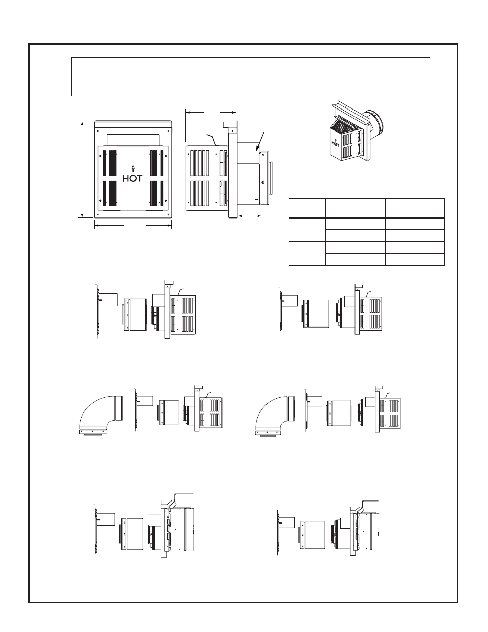
Horizontal Termination Cap
15-1/8 in.
(384 mm)
12 in.
(305 mm)
8 in.
(203 mm)
Max
Effective
Length
Note: Heat shields MUST overlap by a minimum of 1-1/2 in. (38 mm). The heat shield is designed to be
used on a wall 4 in. to 7-1/4 in. (102 mm to 184 mm) thick. If wall thickness is less than 4 in. (102 mm) the
existing heat shields must be field trimmed. If wall thickness is greater than 7-1/4 in. (184 mm) a DVP-HSM-B
will be required.
Heat
Shield
B. Vent Components Diagrams (continued)
Figure 16.5 DVP vent components
Term Cap
Minimum
Effective Length
Maximum
Effective Length
Trap1
3-1/8 in.
4-5/8 in.
79 mm
117 mm
Trap2
5-3/8 in.
9-3/8 in.
137 mm
238 mm