G. wall switch installation for fan (optional), F. junction box installation, Notice: do not wire 110 vac to wall switch – Hearth and Home Technologies GDST4336I User Manual
Page 54
Heatilator • GDST4336I, GDFL4136I, GDCR4136I, GDCL4136I • 2129-900 Rev. F • 11/08
54
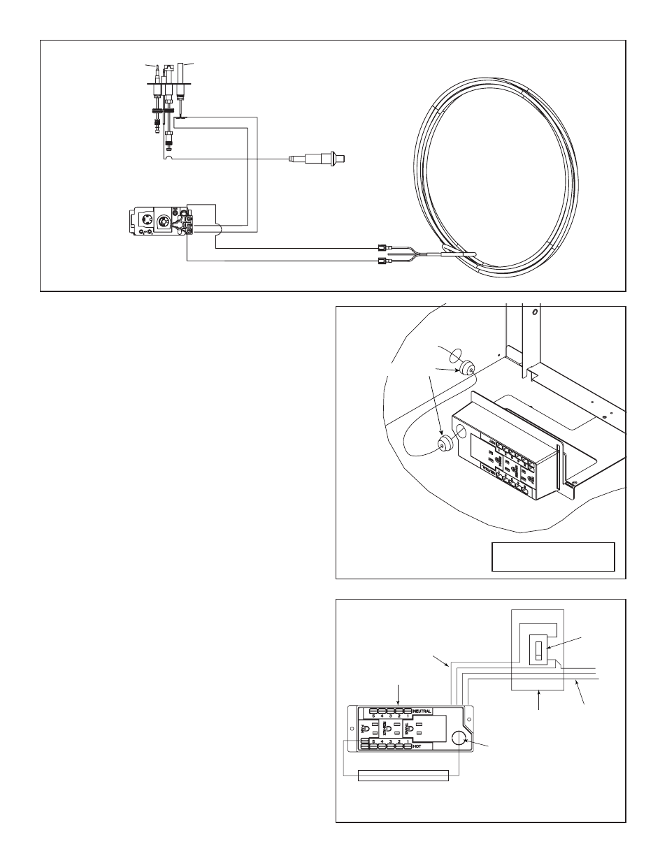
G. Wall Switch Installation for Fan (Optional)
If the box is being wired to a wall mounted switch for use
with a fan (See Figure 12.6):
• The power supply for the appliance must be brought into
a switch box.
• The power can then be supplied from the switch box to
the appliance using a minimum of 14-3 with ground wire.
• At the switch box connect the black (hot) wire and red
(switch leg) wire to the wall switch as shown.
• At the appliance connect the black (hot), white (neutral)
and green (ground) wires to the junction box as shown.
• Add a 1/4 in. insulated female connector to the red (switch
leg) wire, route it through the knockout in the face of the
junction box, and connect to the top fan switch connector
(1/4 in. male) as shown.
ROMEX CONNECTORS
Figure 12.5 Junction Box Detail
NOTICE: DO NOT wire
110 VAC to wall switch.
RED
SWITCH
SWITCH BOX
RED
BLACK
BLACK
GREEN
GREEN
WHITE
POWER
SUPPLY
WIRES
WHITE
RED
BLACK
GREEN
WHITE
MINIMUM 14-3 AWG
WITH GROUND
JUNCTION BOX
KNOCKOUT
Figure 12.6 Junction Box Wired to Wall Switch or BC10
F. Junction Box Installation
The junction box must be wired from the INSIDE of the
appliance:
• Determine which side of the appliance the junction box
is located on.
• Pull the electrical wires from outside the appliance through
the knockout making sure to use a Romex connector to
fasten the electrical wires to the unit.
• Pull enough wire into the valve compartment to easily reach
the junction box location.
• Remove the screw attaching the junction box to the junction
box bracket and set it aside.
• Route the wire through the knockout in the junction box
bracket.
• Wire the junction box and reattach it to the bracket by
inserting the tab in the slot and attaching with screw
previously removed. Ensure that a Romex connector is
used to attach the electrical wires to the junction box.
THERMOSTAT
WIRE ASSEMBLY
PIEZO
WHITE
RED
VALVE
PILOT
THERMOCOUPLE
THERMOPILE
Figure 12.4 Standing Pilot Ignition Wiring Diagram